Integrated X-ray source module

a technology of x-ray source and integrated x-ray, which is applied in the direction of electrical discharge tubes, basic electric elements, electrical equipment, etc., can solve the problems of exacerbating the safety issues of radioactive sources, the intensity of radioactive sources is decaying, and the source is subject to strict regulatory control

Inactive Publication Date: 2005-01-27
NEWTON SCI
View PDF17 Cites 77 Cited by
  • Summary
  • Abstract
  • Description
  • Claims
  • Application Information

AI Technical Summary

Benefits of technology

[0015] In accordance with another aspect of the invention is control electronics used in an X-ray emitter. Electron beam current control electronics controls an electron beam current using a first feedback signal based on current sensing of an emitted beam current. A beam current sense resistor is connected to an anode of an X-ray tube. The beam current sense resistor is used to generate said first feedback signal. High voltage control electronics controls a high voltage power supply using a second feedback signal based on voltage sensing, wherein a resonant converter drives said high voltage power supply.
[0016] In accordance with another aspect of the invention is a method for controlling electron beam current and voltage of an X-ray emitting device drive by a high voltage power supply including: producing a first feedback signal used in electron beam current control electronics that controls an electron beam...

Problems solved by technology

However, the intensity of a radioactive source decays with time requiring frequent recalibration, and radioactive sources are subject to strict regulatory control with respect to transportation, storage and disposal.
Moreover, a radioactive source cannot be turned off when not in use, further exacerbating the safety issues associated with such a source.
They are too bulky, too heavy, and require too much electrical power for field-portable applications.
Radiation shieldin...

Method used


Image

  • Integrated X-ray source module
  • Integrated X-ray source module
  • Integrated X-ray source module

Examples


embodiment 10

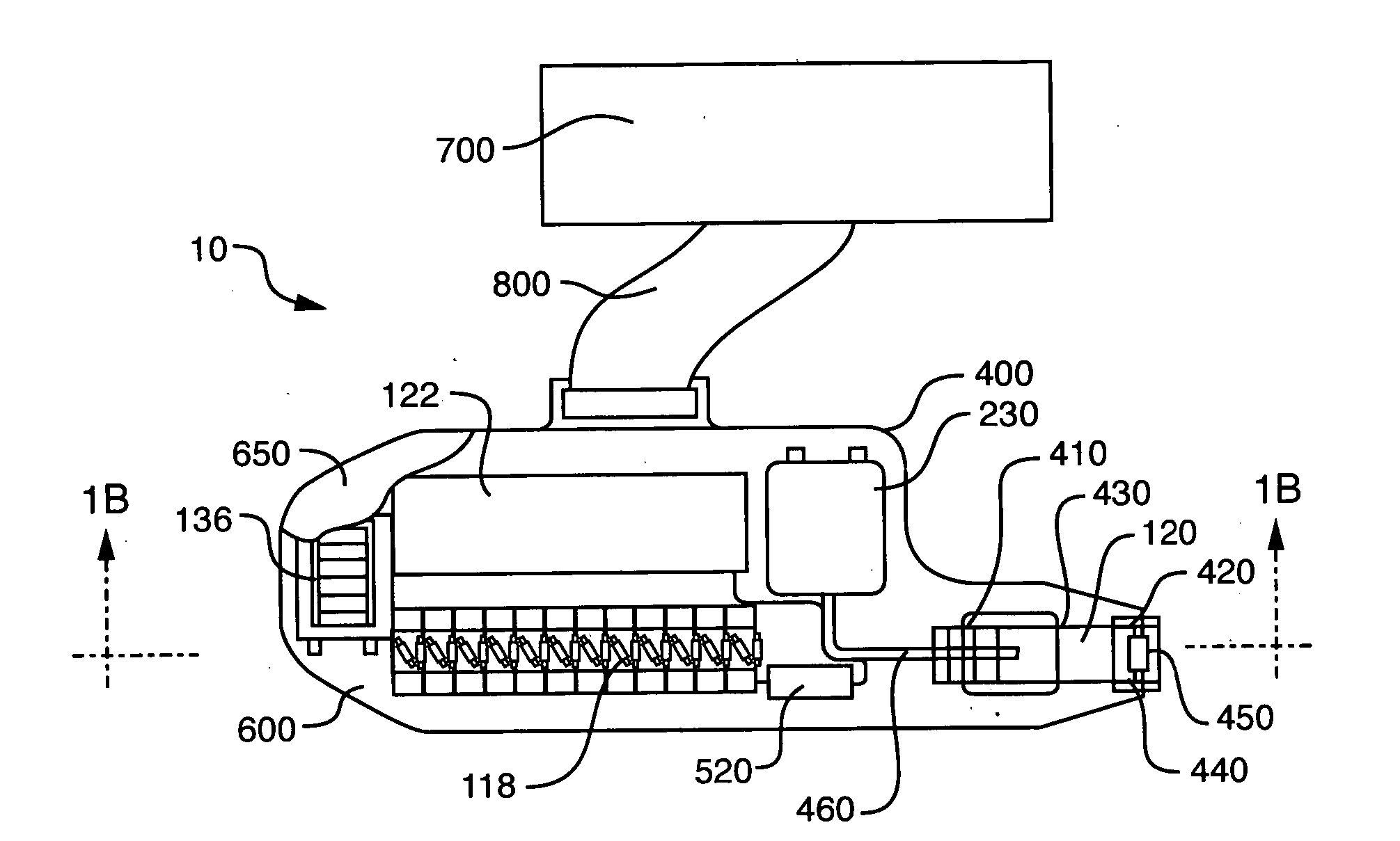
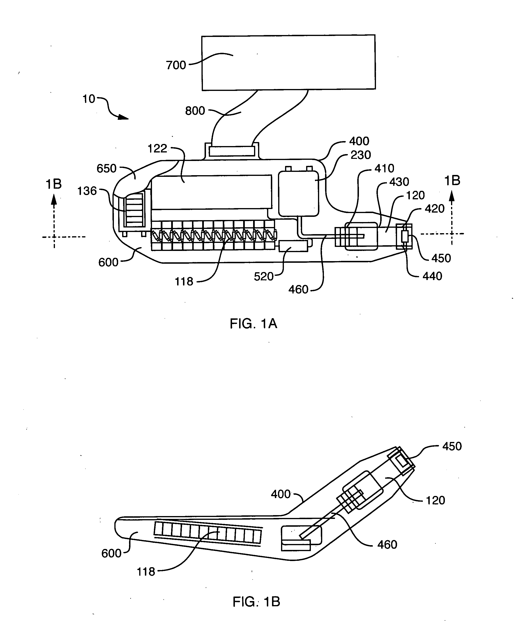
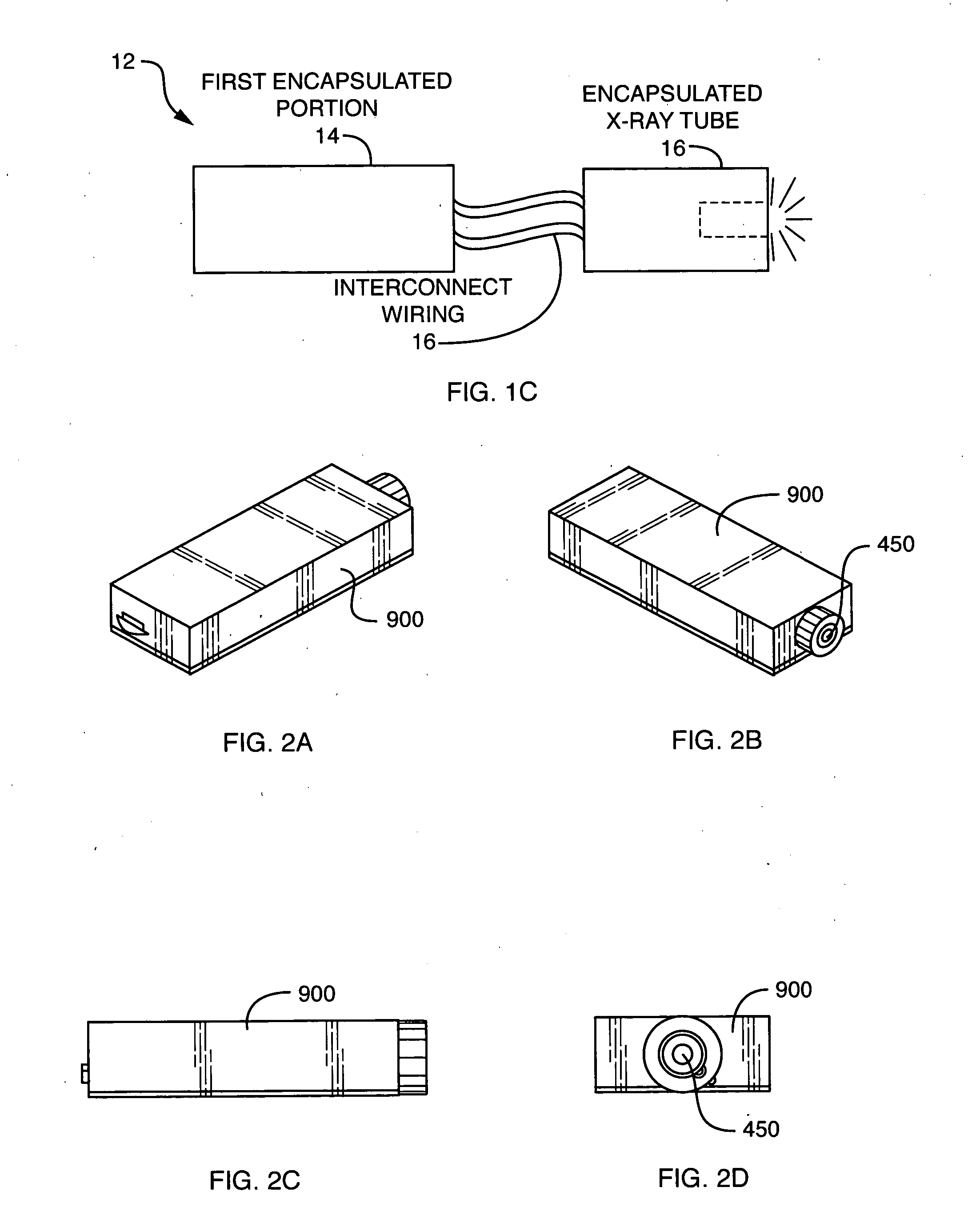
[0034] Referring now to FIG. 1A, shown is an example of an embodiment 10 of a modular unit 400 connected by a cable 800 to a printed circuit board (PCB) 700. Details of the PCB 700 and modular unit 400 are described in more detail in following paragraphs. The modular unit 400 is encased in an electrically insulating potting material 600 and surrounded by a grounded conducting surface 650. The unit 400 is powered by a low voltage power and control circuit on PCB 700 that obtains electrical power from a standard storage battery included thereon. It should be noted that other embodiments may include a battery in an arrangement in which the battery is not located on the PCB 700. The low voltage circuit included on PCB 700 may be located external to the high voltage module unit or modular unit 400, or it may be located within the insulating potting material. In either case, the low voltage circuit is connected to the module via an electrical cable or by another suitable board-to-board co...

embodiment 1000

[0070] Referring now to FIGS. 3A, 4A, 4B and 4C, operation of an embodiment 1000 of a High Voltage Control Loop 1000 and Power Supply 1500 is described. FIGS. 4A, 4B and 4C provide more detail of components included in FIG. 3A. In particular, FIG. 4A is an example of a schematic including the KV Error Processing 128 and the KV Monitor Output Filter 132. FIG. 4B is an example of a schematic including the Resonant Converter 128. FIG. 4C is an example of a schematic including the HV Multiplier Block 118.

[0071] An input control signal, 100, (KV_CTRL) establishes the desired high voltage output 102. A feedback signal, 104, (KV_FDBK) developed from measurement of the actual high-voltage output 102 by a high resistance voltage divider 122 is applied to the positive input of an instrumentation amplifier 130 at U18-3. A ground sense signal 124 (KV_GND_SENSE) is applied to the negative input of this instrumentation amplifier 130 at U18-2. The purpose of this ground sense signal 124 is to corr...


PUM


Abstract

Described is a self-contained, small, lightweight, power-efficient and radiation-shielded module that includes a miniature vacuum X-ray tube emitting X-rays of a controlled intensity and defined spectrum. Feedback control circuits are used to monitor and maintain the beam current and voltage. The X-ray tube, high-voltage power supply, and the resonant converter are encapsulated in a solid high-voltage insulating material. The module can be configured into complex geometries and can be powered by commercially available small, compact, low-voltage batteries.

Description

RELATED APPLICATIONS [0001] This application is a continuation-in-part of U.S. patent application Ser. No. 10 / 370,783, filed Feb. 20, 2003, which claims priority to U.S. Provisional Patent Application No. 60 / 359,169, filed Feb. 20, 2002, both of which are incorporated by reference in their entirety herein.BACKGROUND [0002] 1. Technical Field [0003] This application generally relates to X-ray generation equipment, and more particularly to a small, lightweight, and power-efficient X-ray source module. [0004] 2. Description of Related Art [0005] Devices including X-ray systems are used in the field for a variety of purposes including, for example, XRF (X-ray fluorescence) analysis of metals, ores, soil, water, paints and other materials, identification of taggant materials for security purposes, and analysis of materials in bore holes. Until recently, field-portable XRF instruments used radioactive sources, such as Cd-109, to provide the required X-ray flux. However, the intensity of a...

Claims


Application Information

Patent Timeline
IPC IPC(8): H05G1/06H05G1/10
CPCH05G1/10H05G1/06
Inventor OETTINGER, PETER E.FEDA, FRANCIS M.SHEFER, RUTH E.KLINKOWSTEIN, ROBERT E.
Owner NEWTON SCI
Why Eureka
Try Eureka