Damper mechanism and high pressure fuel pump
a technology of damper mechanism and fuel pump, which is applied in the direction of fuel injecting pump, machine/engine, positive displacement liquid engine, etc., can solve the problems of large space required for welding, increase in the size of damper mechanism or high pressure fuel pump, etc., to reduce the diameter of the metal diaphragm, reduce the pressure pulsation, and reduce the effect of fuel pressure pulsation
- Summary
- Abstract
- Description
- Claims
- Application Information
AI Technical Summary
Benefits of technology
Problems solved by technology
Method used
Image
Examples
first embodiment
[0022] (First Embodiment)
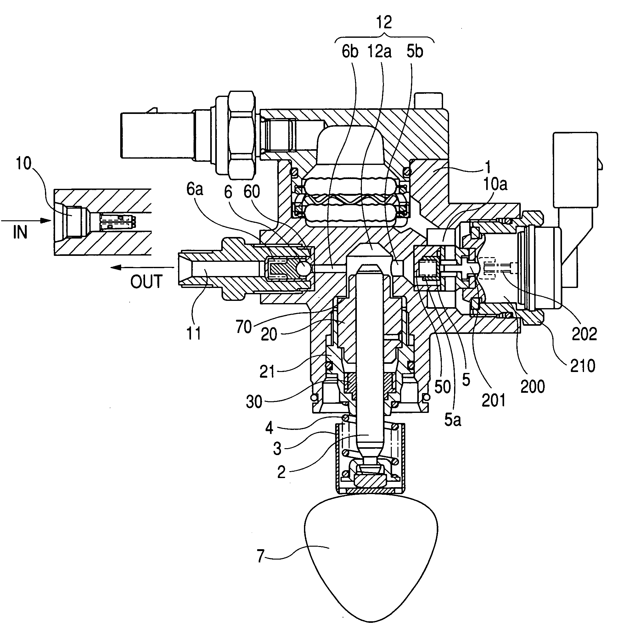
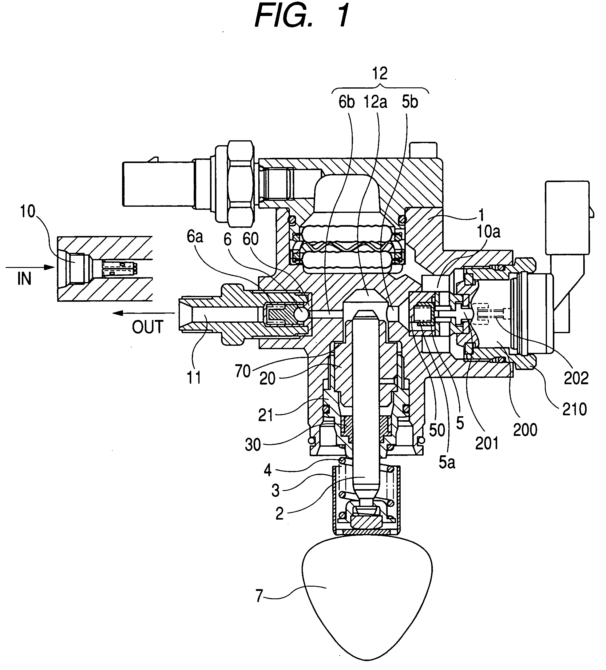
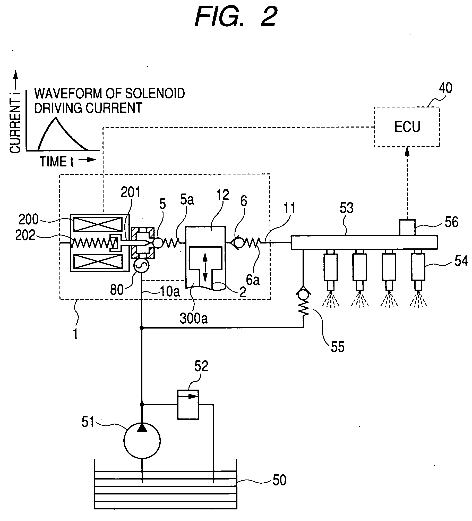
[0023]FIG. 1 is a longitudinal sectional view illustrating the whole of a high pressure fuel pump to which the present invention is applied. FIG. 2 is an overall system diagram illustrating a fuel supply system for internal combustion engine. The figure illustrates a high pressure fuel supply system for use in a direct injection type (cylinder injection type) internal combustion engine.
[0024] An intake joint 10 which forms a fuel intake port and a delivery joint 11 which forms a fuel delivery port are screwed to the main body of the pump (also referred to as “pump body”) 1. A pressure chamber 12 for pressurizing fuel is formed at a fuel passage between the intake joint 10 and the delivery joint 11.
[0025] An intake valve 5 is provided at the inlet of the pressure chamber 12, and a delivery valve 6 is provided at the delivery joint 11. The intake valve 5 and the delivery valve 6 are respectively energized by springs 5a and 6a in such a direction as to close ...
second embodiment
[0052] (Second Embodiment)
[0053] Next, another embodiment of the present invention will be described referring to FIG. 4.
[0054] In this embodiment, as a mechanism for reducing fuel pressure pulsation, two double metal diaphragm dampers 80 and 81 are provided at a fuel passage between the intake joint 10 and the intake chamber (low pressure chamber) 10a.
[0055] The double metal diaphragm damper 80 has its rim clamped between the washer 103 and the washer guide 102 over the entire circumference like the first embodiment. The washer 103 is provided with the same chamfers on the outer diameter sides of its both sides. The washer 103 is machined so that its diameter is same as the diameter of the rim of the double metal diaphragm damper 80. The washer guide 102 is provided with an annular groove 102a. The fuel chambers 10b and 10c are connected to the fuel chamber (intake chamber) boa.
[0056] The double metal diaphragm damper 81 has the rim clamped between the washer 103 and the damper ...
third embodiment
[0062] (Third Embodiment)
[0063] Next, a further embodiment of the present invention will be described referring to FIG. 5.
[0064] As a mechanism to reduce fuel pressure pulsation, two double metal diaphragm dampers 80 and 81 are provided between the fuel passage 10 and the low pressure chamber 10a. The metal diaphragm dampers 80 and 81 are different from each other in cross-sectional shape.
[0065] The two double metal diaphragm dampers 80 and 81 have their rims clamped between each washer 103 and each washer guide 102 over the entire circumference. The washers 103 are provided with the same chamfers on the outer diameter sides of its both sides. The rims of the washers 103 are machined to the same dimensions as the rims of the double metal diaphragm dampers 80 and 81. The washer guides 102 are provided with each annular groove 102a. Further, the fuel chambers 10b, 10c, and 10d are connected to the fuel chamber (intake chamber) 10a.
[0066] A spring 104 is provided between the two was...
PUM
 Abstract
Description
Claims
Application Information
 - R&D
- Intellectual Property
- Life Sciences
- Materials
- Tech Scout
- Unparalleled Data Quality
- Higher Quality Content
- 60% Fewer Hallucinations
Browse by: Latest US Patents, China's latest patents, Technical Efficacy Thesaurus, Application Domain, Technology Topic, Popular Technical Reports.
© 2025 PatSnap. All rights reserved.Legal|Privacy policy|Modern Slavery Act Transparency Statement|Sitemap|About US| Contact US: help@patsnap.com


