Automatic crown and gingiva detection from three-dimensional virtual model of teeth

a three-dimensional virtual model and automatic technology, applied in the field of automatic crown and gingiva detection from three-dimensional virtual model of teeth, can solve the problems of large volume of images and data involved, limited in their functionalities and scope, and substantial manual work involved in these steps

Active Publication Date: 2005-01-27
ORAMETRIX
View PDF13 Cites 78 Cited by
  • Summary
  • Abstract
  • Description
  • Claims
  • Application Information

AI Technical Summary

Problems solved by technology

Thus, there is a large volume of images and data involved in the diagnosis and treatment planning process.
There are some computerized tools available to aid the practitioner in these data conversion and reduction steps, for example to convert cephalometric x-rays (i.e., 2 dimensional x-ray photographs showing a lateral view of the head and jaws, including teeth) into points of interest with respect to soft tissue, hard tissue, etc., but they are limited in their functionalities and scope.
Even then, there is a fairly substantial amount of manual work involved in these steps.
However, such models allow free movement of teeth without regard to the patient's biological constraints, and can frequently lead to impractical treatment set-ups.
Generally, these steps are time consuming and prone to inherent inaccuracies.
Furthermore, the practitioner has to contend with the biological interdependencies within the patient, which introduces constraints eliminating certain treatment options that would otherwise be acceptable, between the soft tissue, the hard tissue, and the teeth.
There is lack of an integrated platform which a practitioner could utilize to filter-out non-practicable treatment options.
Often, due to the complexities of the detailed steps and the time consuming nature of them, some practitioners take a short cut, relying predominantly on their intuition to select a treatment plan.
All of these factors frequently contribute towards trial and error, hit-and-miss, lengthy and inefficient treatment plans that require numerous mid-course adjustments.
While at the beginning of treatment things generally run well as all teeth start to move at least into the right direction, at the end of treatment a lot of time is lost by adaptations and corrections required due to the fact that the end result has not been properly planned at any point of time.
By and large, this approach lacks reliability, reproducibility and precision.
More over, there is no comprehensive way available to a practitioner to stage and simulate the treatment process in advance of the actual implementation to avoid the often hidden pitfalls.
And the patient has no choice and does not know that treatment time could be significantly reduced if proper planning was done.
A 3D scanned model of a patient's dentition, whether taken in-vivo or from a physical model, typically covers the surfaces of all teeth and parts of the surrounding gum, but there can also be gaps in it, i.e. parts of teeth and gum the 3D scan did not reach.
However, these approaches are limited to diagnosis and treatment planning of craniofacial structures, including the straightening of teeth.

Method used


Image

  • Automatic crown and gingiva detection from three-dimensional virtual model of teeth
  • Automatic crown and gingiva detection from three-dimensional virtual model of teeth
  • Automatic crown and gingiva detection from three-dimensional virtual model of teeth

Examples


Embodiment Construction

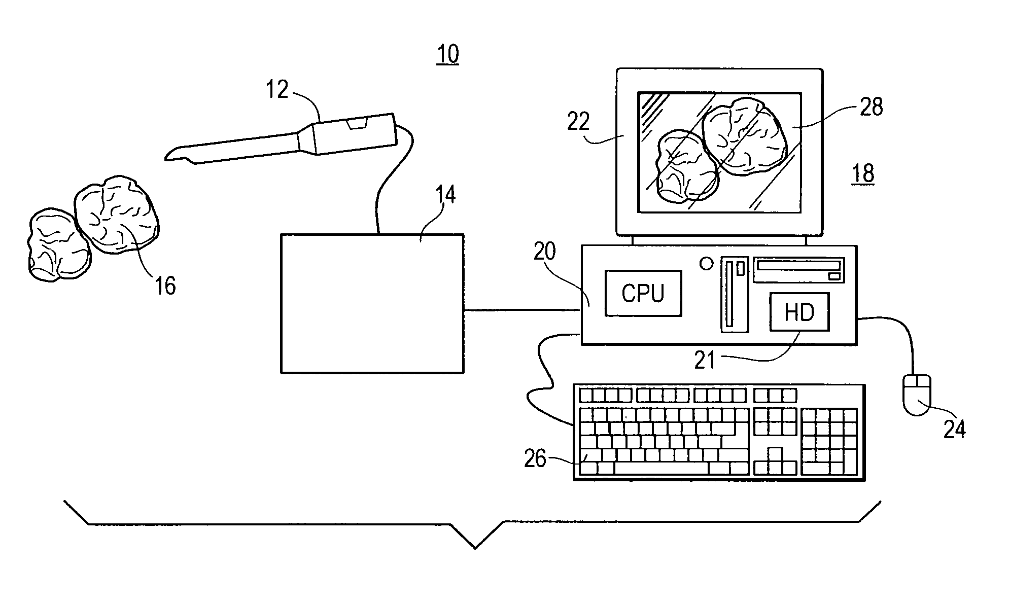
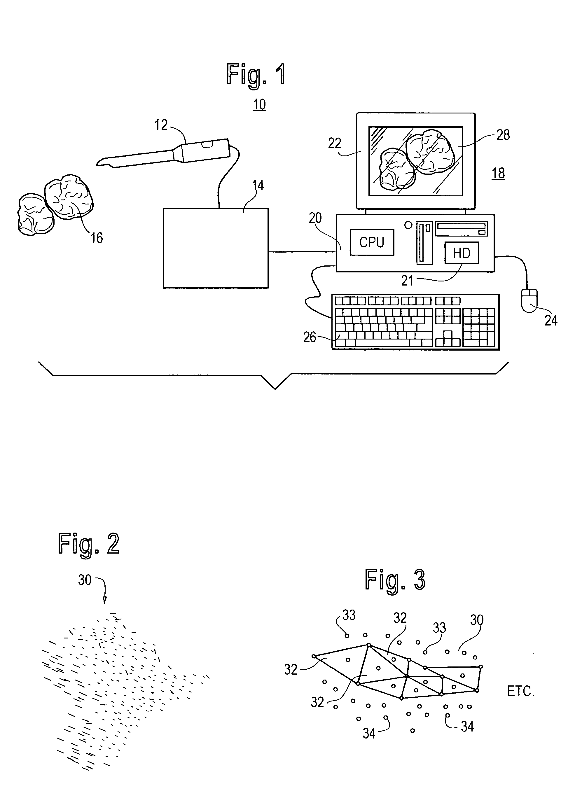
FIG. 1 is a schematic diagram of one possible environment in which the invention can be practiced. A scanner 10 consisting of an optical probe unit 12 and scanner electronics module 14 conducts a 3D scan of an object 16. The object 16 can be virtually anything. In the present example. the object 16 consists of dentition 15 and associated anatomical structures (gingival tissue) 17. The scan of the dentition and gum tissue could be obtained either in-vivo, or it could be made from a physical model of the dentition and associated anatomical structures. The present invention is not limited to the particular manner in which the virtual model of the dentition and gingival tissue is obtained. For example, the scanner could be a laser scanner or destructive scanner. In the illustrated embodiment, the scanner is a hand-held in-vivo scanner as described in the published PCT application of OraMetrix, publication no. WO 01 / 80761, the contents of which are incorporated by reference herein. An op...


PUM


Abstract

A method is provided for automatically separating tooth crowns and gingival tissue in a virtual three-dimensional model of teeth and associated anatomical structures. The method orients the model with reference to a plane and automatically determines local maxima of the model and areas bounded by the local maxima. The method automatically determines saddle points between the local maxima in the model, the saddle points corresponding to boundaries between teeth. The method further positions the saddle points along a dental arch form. For each tooth, the method automatically identifies a line or path along the surface of the model linking the saddle points to each other, the path marking a transition between teeth and gingival tissue and between adjacent teeth in the model. The areas bounded by the lines correspond to the tooth crowns; the remainder of the model constitutes the gingival tissue.

Description

BACKGROUND OF THE INVENTION A. Field of the Invention This invention is directed to an interactive workstation and associated computerized techniques for facilitating detection of individual teeth boundaries and gingival boundaries from a three-dimensional virtual computer model of teeth: The identification and separation of the teeth from the gingival tissue has applications in digital dentistry and orthodontics. For example, the separation of the teeth from the gingiva is typically a preliminary step in planning of treatment for orthodontic patients on a computer. B. Description of Related Art The traditional process of diagnosis and treatment planning for a patient with orthodontic problems or disease typically consists of the practitioner obtaining clinical history, medical history, dental history, and orthodontic history of the patient supplemented by 2D photographs, 2D radiographic images, CT scans, 2D and 3D scanned images, ultrasonic scanned images, and in general non-in...

Claims


Application Information

Patent Timeline
Patent Type & Authority Applications(United States)
IPC IPC(8): A61C7/00A61C9/00G06T5/00
CPCA61C7/00A61C7/002A61C9/00A61C9/004A61C2007/004G06T2207/30036G06T7/0083G06T2200/04G06T2200/24G06T2207/10028G06T7/0012A61C9/0053G06T7/12
Inventor KAUFMANN, MARKUSSPORBERT, PEERGETTO, PHILLIP
Owner ORAMETRIX
Why Eureka
Try Eureka