Parachute for low altitude deployment

a low-altitude deployment and parachute technology, applied in the field of parachutes, can solve the problems of insufficient opening speed unsuitable parachutes for low-speed deployment, and insufficient stability of standard parachute canopies, etc., to achieve the effect of stable state shape and internal pressur

Inactive Publication Date: 2005-01-27
EMERGENCY EVACUATION SYST
View PDF1 Cites 2 Cited by
  • Summary
  • Abstract
  • Description
  • Claims
  • Application Information

AI Technical Summary

Benefits of technology

[0013] Accordingly, one feature, aspect or advantage of certain embodiments of the present invention provides parachutes used in low speed deployment at low altitude, such as emergency evacuations from buildings. In particular, one feature, aspec

Problems solved by technology

Most parachutes are unsuitable for low speed deployments, such as those involving jumps at lower altitudes from a fixed object.
For instance, most parachutes are not suitable for use during an emergency evacuation from a building.
Standard parachute canopies do not open fast enough when deployed at low speeds.
The deployment difficulties experienced at low speeds is disadvantageous when parachuting from buildings because the initial speed upon exiting the building is quite low.
Unfortunately, once sufficient speed has been obtained, standard parachute canopies may not sufficiently slow the evacuee's descent speed within the remainder of the descent such that the likelihood of serious injury or death can be reduced or eliminated.
During a pulse, the user may experience a higher than normal deceleration in the rate of descent, which can result in high g-forces being transmitted to the user.
As can be expected, each pulse can result an undesirable shock to the user.
Furthermore, when the canopy flattens during a pulse, the canopy tends to slip sideways through the air while the user falls generally downward.
Even after reaching a steady-state condition, standard parachute canopies tend to behave somewhat like an airfoil in turbulent or windy conditions because of low internal volumes and pressures.
The combination of side slip and downward acceleration of the user can cause the user to swing like a pendulum.
The combination also can lead to oscillations, resulting in a similar pendulum effect and reducing the stability of the descent.
In extreme situations, the canopy may even collapse.
In addition, during building evacuations, sufficient forward speed wou

Method used


Image

  • Parachute for low altitude deployment
  • Parachute for low altitude deployment
  • Parachute for low altitude deployment

Examples


Embodiment Construction

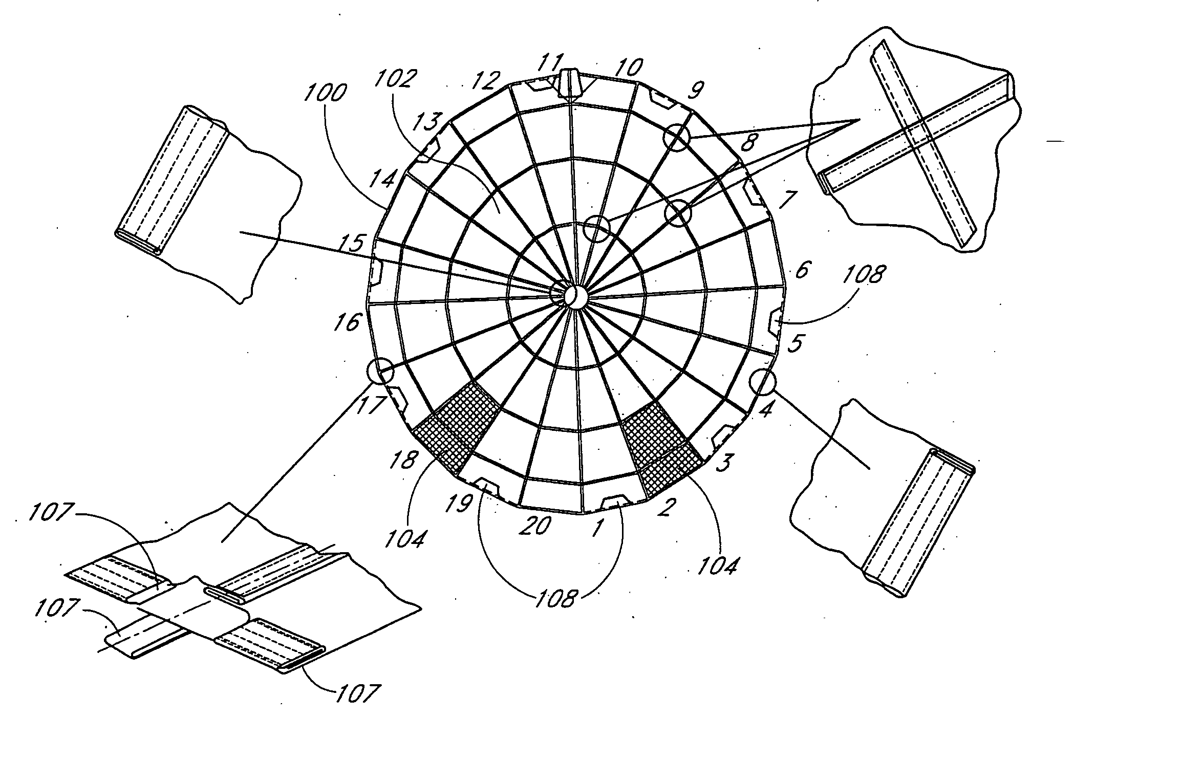
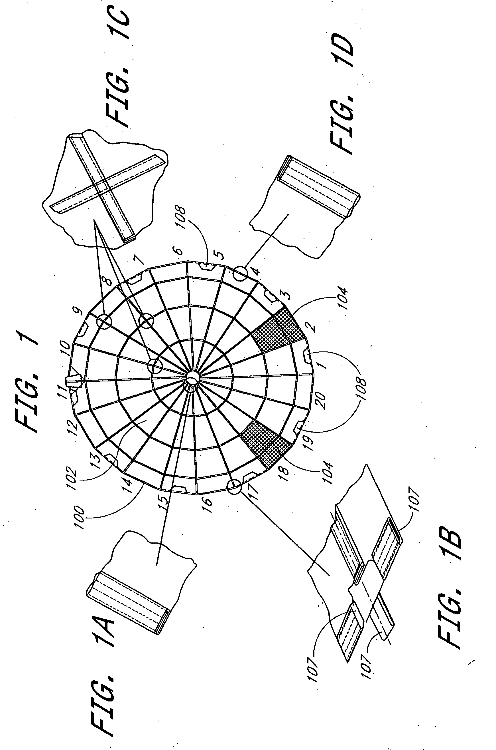
[0032] With reference to the figures, certain embodiments of the present invention will be described, which embodiments provide parachutes that are particularly adapted for use in low speed deployments at low altitudes, such as emergency evacuations from buildings.

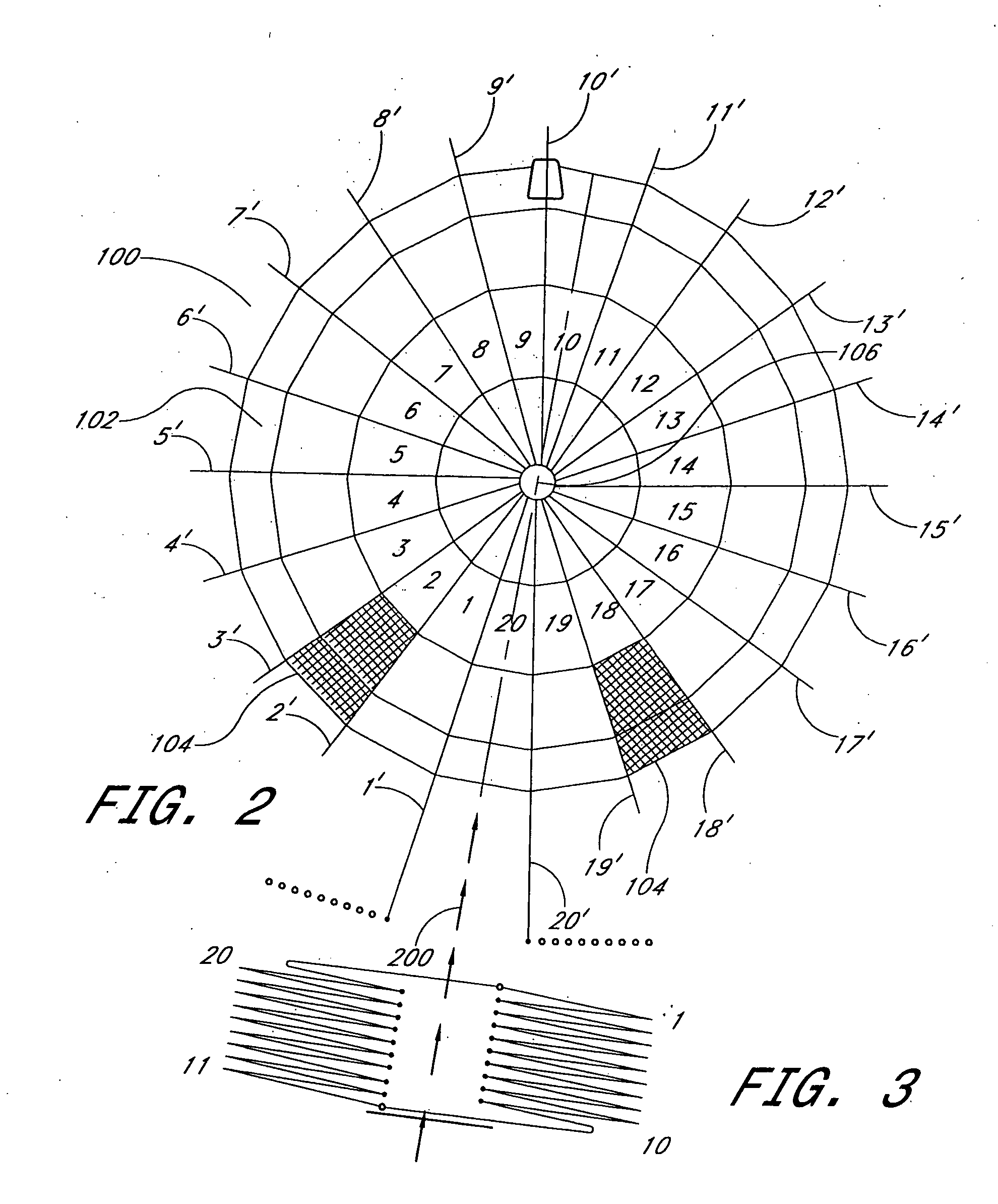
[0033] One particularly preferred parachute features, among other components, a conical canopy that results in a greater internal volume and pressure as compared to many conventional parachute canopies. The greater internal volume and pressure of the conical canopy greatly reduces the pulse effect upon opening of the canopy, which helps stabilize the parachute during descent. A top polar opening in the canopy also helps stabilize the descent of the parachute, by allowing some of the air in the canopy to escape, thereby reducing the amount of air spilling out from the perimeter of the canopy. Two porous sections in the rear of the canopy create two airflow streams during descent, generating forward speed and enabling the p...


PUM


Abstract

A parachute is adapted for deployment at low altitudes and low air speeds, such as for use in emergency evacuations from buildings. A canopy of the parachute includes a conical portion with a top polar opening. The canopy also includes a porous section that create an airflow stream during descent, generating forward speed and enabling the parachute to be steered during descent. The materials used in the canopy lines and the harness help reduce shocks and help to sustain a substantially steady-state internal air pressure in the canopy. A method for folding the parachute helps to reduce the time to deployment.

Description

RELATED APPLICATION [0001] This application claims priority pursuant to 35 U.S.C. 119(e) to co-pending U.S. Provisional Patent Application Ser. No. 60 / 455,077, filed Mar. 13, 2003, which is hereby incorporated by reference in its entirety.BACKGROUND OF THE INVENTION [0002] 1. Field of the Invention [0003] The present invention generally relates to parachutes. More specifically, the present invention relates to parachutes that are adapted for use in low altitude situations. [0004] 2. Description of the Related Art [0005] Most parachutes are unsuitable for low speed deployments, such as those involving jumps at lower altitudes from a fixed object. For instance, most parachutes are not suitable for use during an emergency evacuation from a building. This is especially true when an untrained evacuee is using the parachute for such an emergency evacuation. [0006] Standard parachute canopies do not open fast enough when deployed at low speeds. This is due, in part, to the physics involved...

Claims


Application Information

Patent Timeline
IPC IPC(8): B64D17/02B64D17/30B64D17/40
CPCB64D17/02B64D17/40B64D17/30
Inventor STRAKA, JOSEFNOSEK, PREMYSL
Owner EMERGENCY EVACUATION SYST
Why Eureka
Try Eureka