Operation microscope

Inactive Publication Date: 2005-01-27
OLYMPUS CORP
View PDF14 Cites 166 Cited by
  • Summary
  • Abstract
  • Description
  • Claims
  • Application Information

AI Technical Summary

Benefits of technology

[0006] The present invention has been developed in consideration of the aforementioned situations, and an object thereof is to provide an operation microscope by which an endoscope observation image for observing a dead angle of a microscope observation image, image information of a microscope or endoscope observa

Problems solved by technology

However, in the aforementioned prior art, since the size or the like of the in-field display image displayed in the field of the microscope observation image cannot be freely changed, the image display itself can possibly interfere with the orientation handling

Method used


Image

  • Operation microscope
  • Operation microscope
  • Operation microscope

Examples


first embodiment

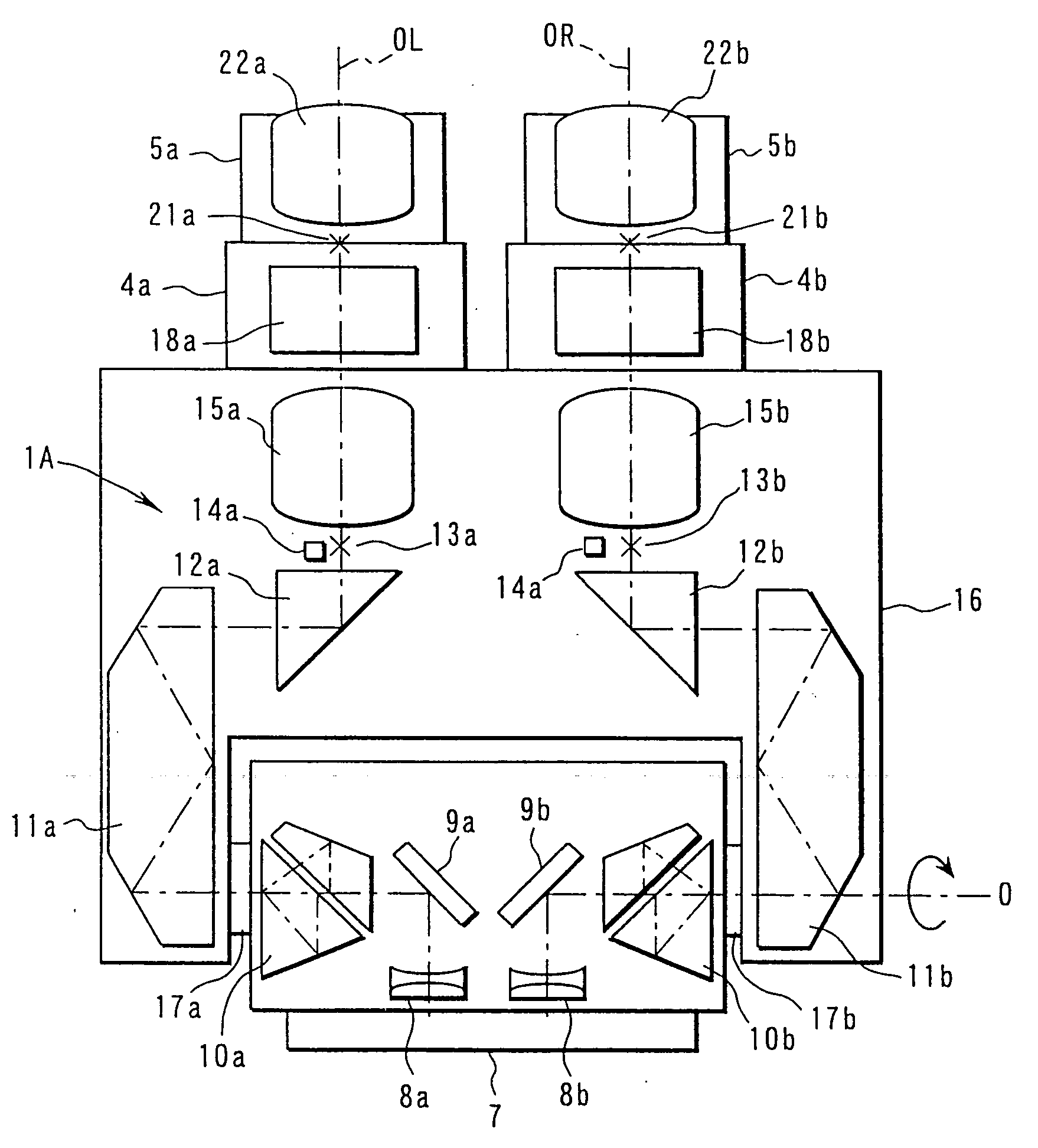
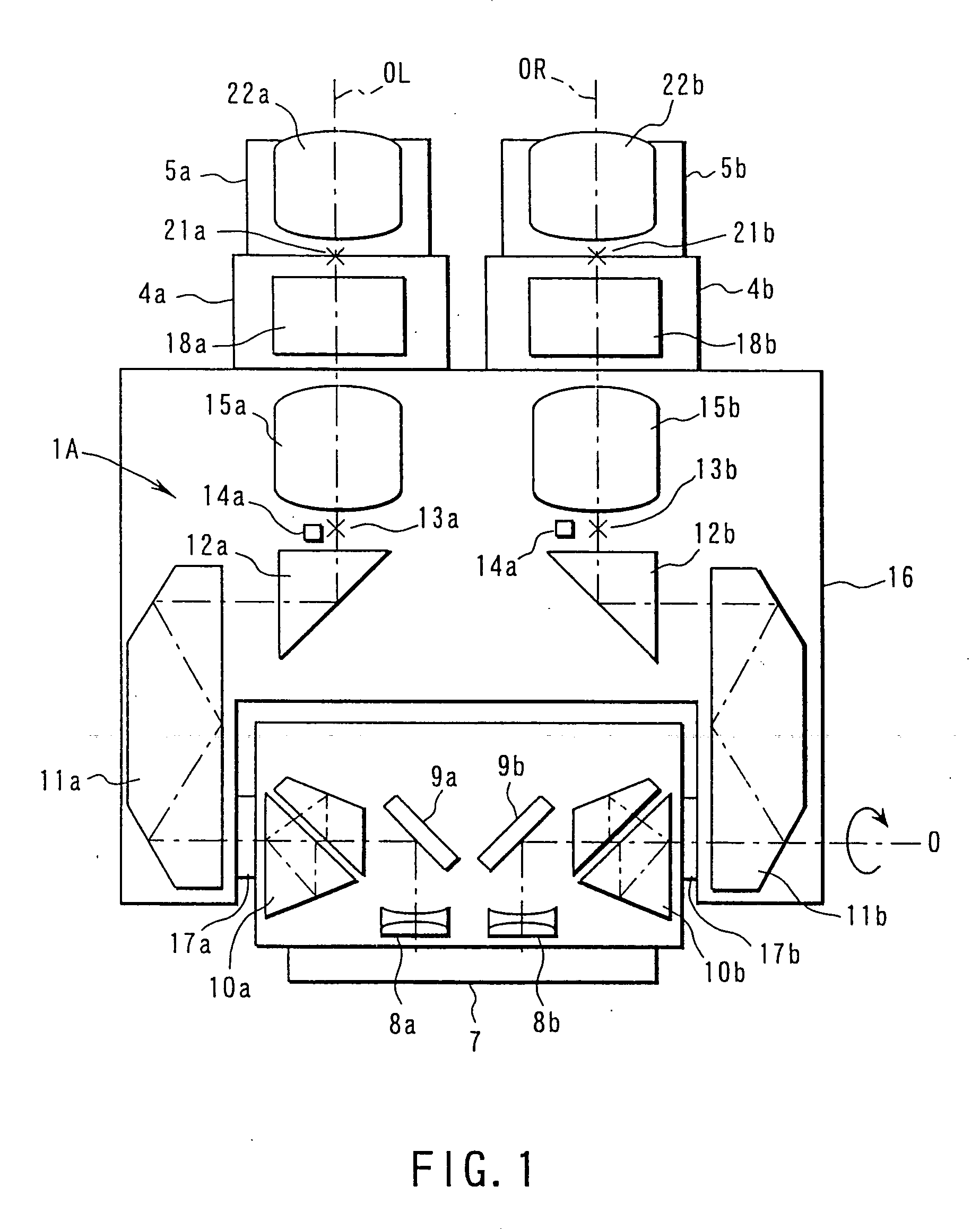
[0115]FIG. 1 to FIG. 8 show a FIG. 1 shows an internal optical system constitution of a binocular eyepiece lens tube of an operation microscope 101 (see FIG. 6), and FIG. 2 is a diagram showing a left side optical observation system of FIG. 1. Additionally, a right side optical observation system of the binocular eyepiece lens tube has the same constitution as that of the left optical observation system of FIG. 2, and only the constitution of the left side optical observation system of FIG. 2 will be described here.

[0116] As shown in FIG. 1, a fixed housing 7, and a movable housing 16 are disposed in a microscope body 104 (see FIG. 6) of the binocular eyepiece lens tube of the operation microscope 101 of the present embodiment. A pair of left and right image forming lenses 8a, 8b are disposed inside the fixed housing 7. The respective image forming lenses 8a, 8b are optically connected to a first optical observation system 1A. Additionally, besides the first observation optical sys...

second embodiment

[0165] Moreover, FIG. 9 to FIG. 12 show the present invention. The second embodiment is obtained by changing the constitution of the operation microscope 101 of the first embodiment (see FIG. 1 to FIG. 8) as follows.

[0166] That is, in the second embodiment, an image input function from the nerve monitor 100 as an operation diagnosis apparatus for checking a function of a cranial nerve is added to the constitution of the operation microscope 101 of the first embodiment. Furthermore, waveform monitor means for monitoring a waveform of the nerve monitor 100 is disposed, the result is used to change the display state of the nerve monitor 100 in accordance with the state of the waveform monitor means, and the waveform can be displayed in the microscope observation field O.

[0167]FIG. 9 is a block diagram for monitoring the nerve monitor 100. Here, a setting input section 151 is connected to an image converter 153 via a comparison calculator 152. The nerve monitor 100 is connected to the ...

third embodiment

[0176] That is, the third embodiment additionally includes a function of transmitting a microscope observation image O photographed in an operating theater to a conference room outside the operating room, so that input image information can be displayed in an image display of the microscope 101 in the operating theater by pen touch input in an external conference room. Thereby, an instruction can directly be given to the operating person who is carrying out the operation from an external conference room.

[0177] In FIG. 13, numeral 155 denotes an operating theater, and 156 denotes a conference room. The rooms are partitioned by a wall 157. The microscope observation image of the operation microscope 101 photographed in the operating theater 155 is transmitted to a monitor 160 via an image synthesis apparatus 159 of the conference room 156 from an interface 158. Thereby, as shown in FIG. 14, the microscope observation image O of the operation microscope 101 is displayed in the monitor ...


PUM


Abstract

There is disclosed an operation microscope in which an observing and displaying system of an operating instrument are selected, and an endoscope image for observing a dead angle of the microscope and a navigation image are selectively displayed in a microscope observation field, so that a tomographic image, three-dimensionally constructed image, and the like can be selectively displayed in a display screen in accordance with a treatment position displayed in a monitor or an observation position of the operation microscope.

Description

CROSS-REFERENCE TO RELATED APPLICATIONS [0001] This application is based upon and claims the benefit of priority from the prior Japanese Patent Applications No. 2000-119995, filed Apr. 20, 2000; No. 2000-180224, filed Jun. 15, 2000; No. 2000-191476, filed Jun. 26, 2000; No. 2000-193223, filed Jun. 27, 2000; and No. 2000-194807, filed Jun. 28, 2000, the entire contents of all of which are incorporated herein by reference. BACKGROUND OF THE INVENTION [0002] The present invention relates particularly to an operation microscope for use in a surgical operation of a fine portion in cranial nerve surgery, and the like. [0003] In conventional cranial nerve surgery, to absolutely perform a delicate operation, an operation microscope for stereoscopically enlarging an image of a portion being subjected to the operation has been utilized in many cases. Furthermore, in recent years, to certainty carry out an operation, endoscope observation is performed in a conventional operation concurrently w...

Claims


Application Information

Patent Timeline
IPC IPC(8): A61B1/00A61B1/04A61B8/12G02B21/00G02B21/22H04N13/02
CPCA61B1/00039A61B1/0005A61B1/00147A61B1/00149A61B1/00188A61B8/0816A61B8/12A61B8/4245A61B8/5238G02B21/0012G02B21/22A61B1/042A61B1/00042
Inventor SHIODA, KEIJINAKANISHI, KAZUHITOMIZOGUCHI, MASAKAZUFUKAYA, TAKASHIOHNO, WATARUKINUKAWA, MASAHIKOUEDA, MASAAKINAKAMURA, MOTOKAZUSHINMURA, TORUMORITA, KAZUO
Owner OLYMPUS CORP
Why Eureka
Try Eureka