

Cultivator for aerating a ground surface
Patent Information
- Authority / Receiving Office
- US · United States
- Patent Type
- Applications(United States)
- Current Assignee / Owner
- DEERE & CO
- Publication Date
- 2005-02-03
- Estimated Expiration
- Not applicable · inactive patent
Smart Images
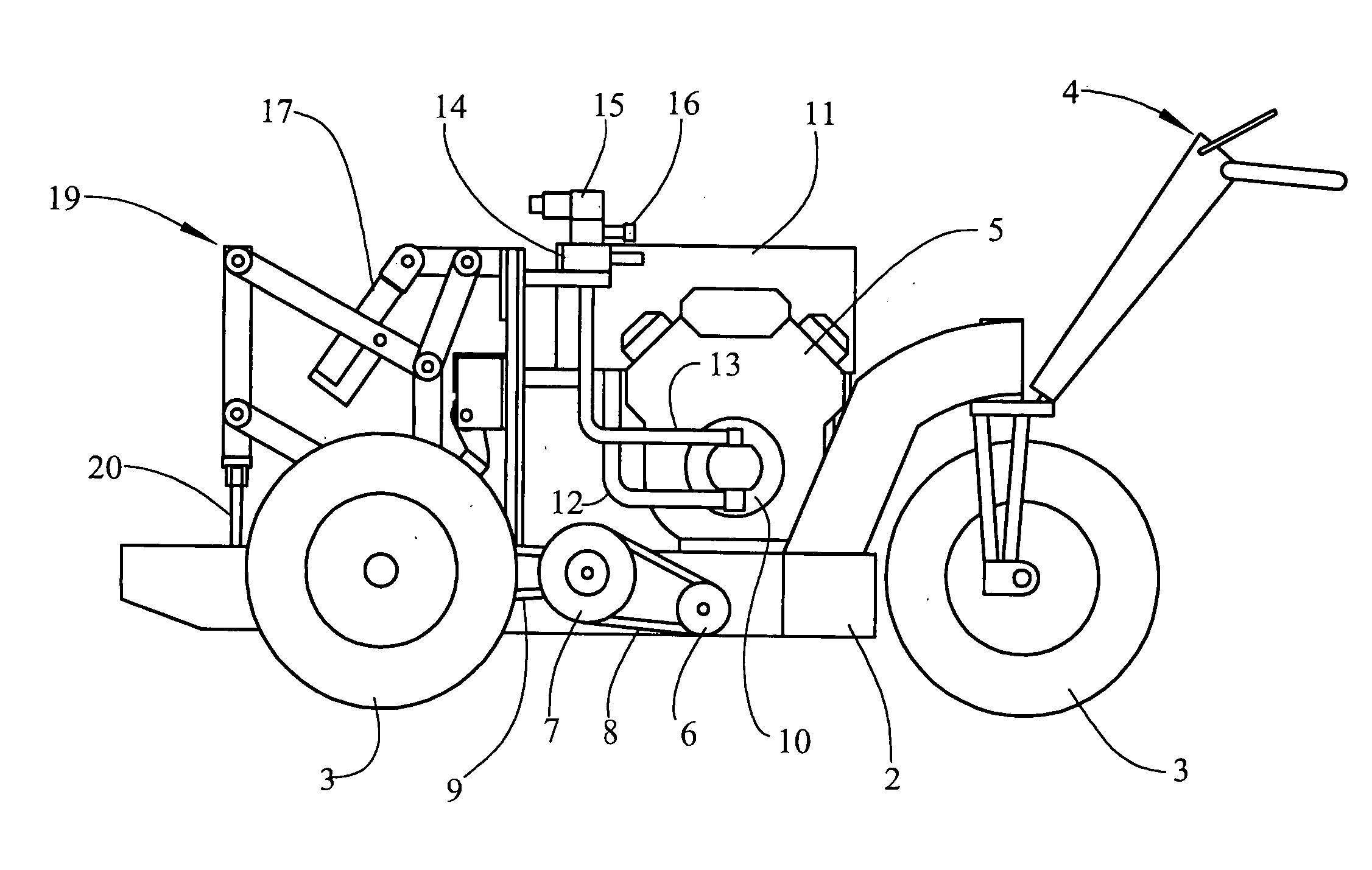
Figure 1 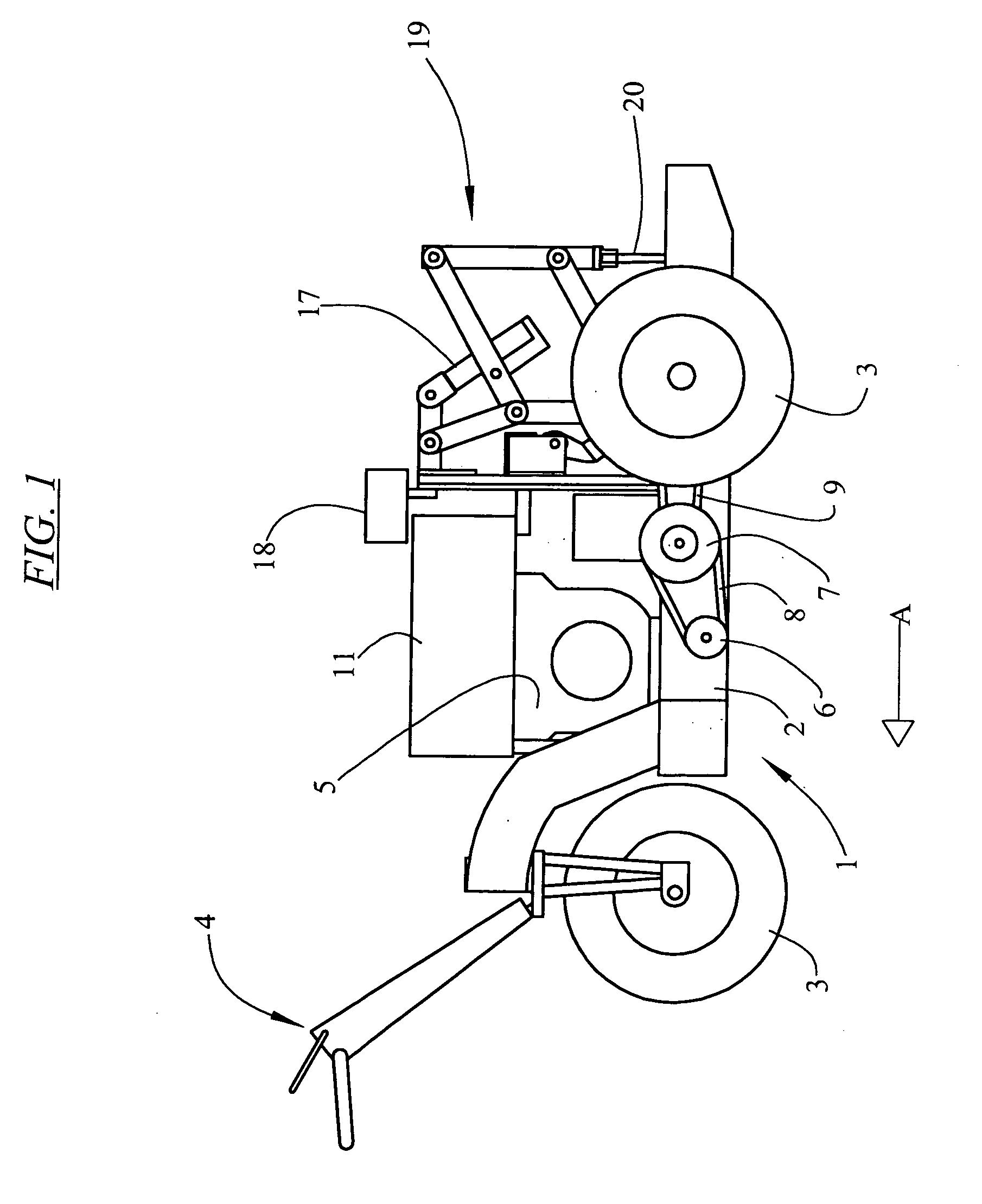
Figure 2 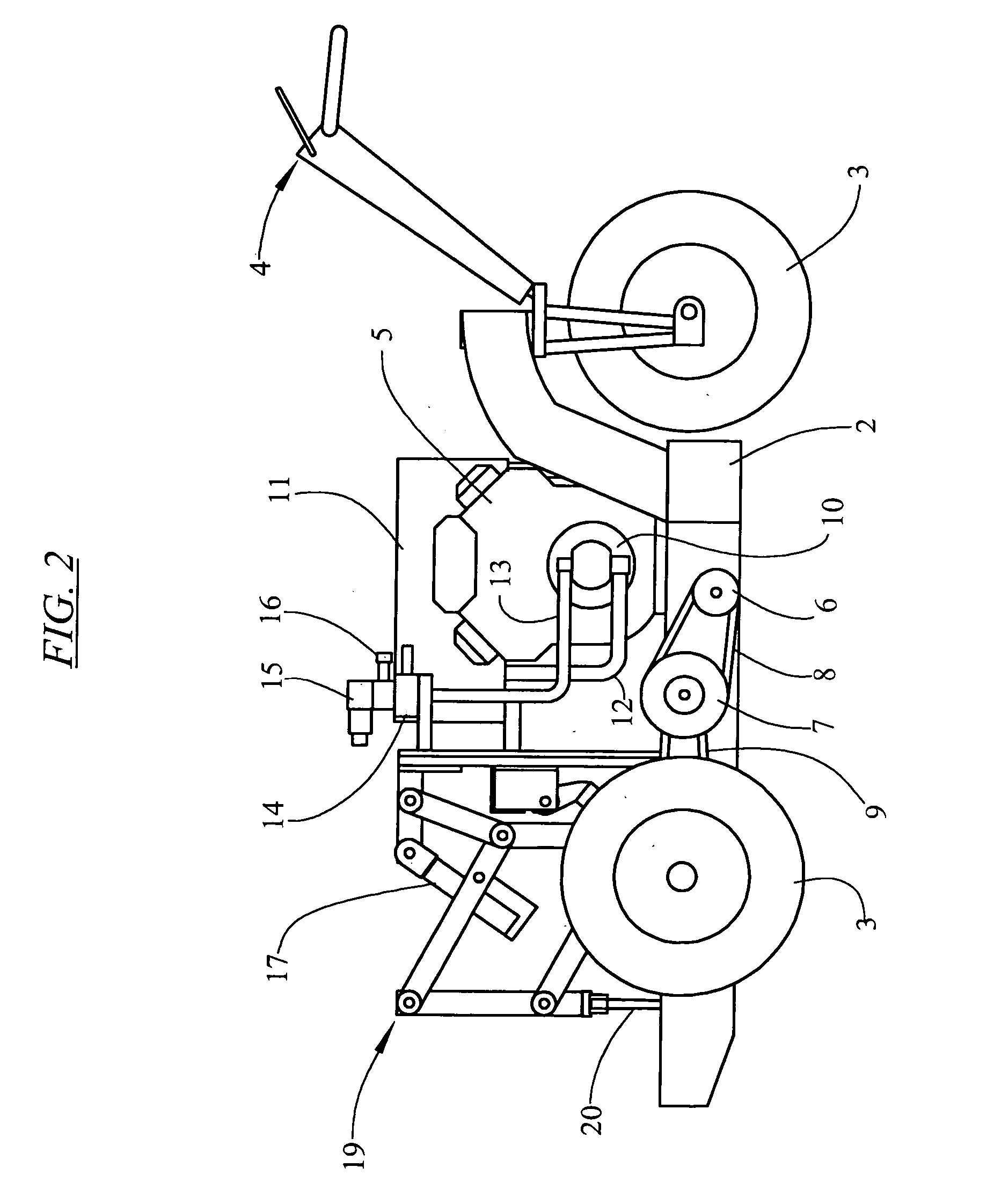
Figure 3
Abstract
Description
FIELD OF THE INVENTION
[0001] This invention relates to a cultivator for aerating ground surfaces. The invention has particular application to cultivators for aerating turf surfaces, such as golf courses, sporting grounds, bowling greens and the like. BACKGROUND ART
[0002] Cultivators of this type are used for maintaining landscaped ground surfaces, including turf. In this sense the term “turf” refers to grass and other material which is specifically grown for playing sport and used for example to form golf course greens, sporting fields and bowling greens. Cultivators are frequently used on these types or surfaces for repeatedly penetrating the ground surface, forming a plurality of holes so that the ground surface is aerated, to improve growth of the grass or other material and enhance the condition of the surface for playing purposes.
[0003] In conducting this type of aeration of turf surfaces, the neatness of the edges of the hole made by the cultivator can significantly affect ...