Soft-switching three-phase power factor correction converter

a three-phase power factor and converter technology, applied in the field of soft-switching three-phase power factor correction converters, can solve the problems of relatively high switching loss of active switch s, relatively heavy and larger industry, and relatively large size of the industry of silicon steel industries, so as to reduce the size of the magnetic elements of the converter and reduce the thd

Inactive Publication Date: 2005-02-03
DELTA ELECTRONICS INC
View PDF1 Cites 18 Cited by
  • Summary
  • Abstract
  • Description
  • Claims
  • Application Information

AI Technical Summary

Benefits of technology

[0006] It is therefore an object of the present invention to propose a soft-switching three-phase power factor correction converter for correcting the power factor, lowering the THD, and decreasing the sizes of the magnetic elements of the converter relatively.

Problems solved by technology

Besides, the inductors of the above-mentioned apparatus, made of silicon steel, are relatively heavier and larger.
Firstly, there are relatively higher switching losses of the active switch S due to the reverse recovery time of the diode Db.
Secondly, the desired requirements of decreasing the sizes of the magnetic elements for the apparatus of FIG. 2 are infeasible since the switching frequency must be increased in order to do so and which will result in the relatively higher switching losses.
Thirdly, the desired requirement of having a THD less than 5% could not be achieved by the apparatus as shown in FIG. 2.

Method used


Image

  • Soft-switching three-phase power factor correction converter
  • Soft-switching three-phase power factor correction converter
  • Soft-switching three-phase power factor correction converter

Examples


Embodiment Construction

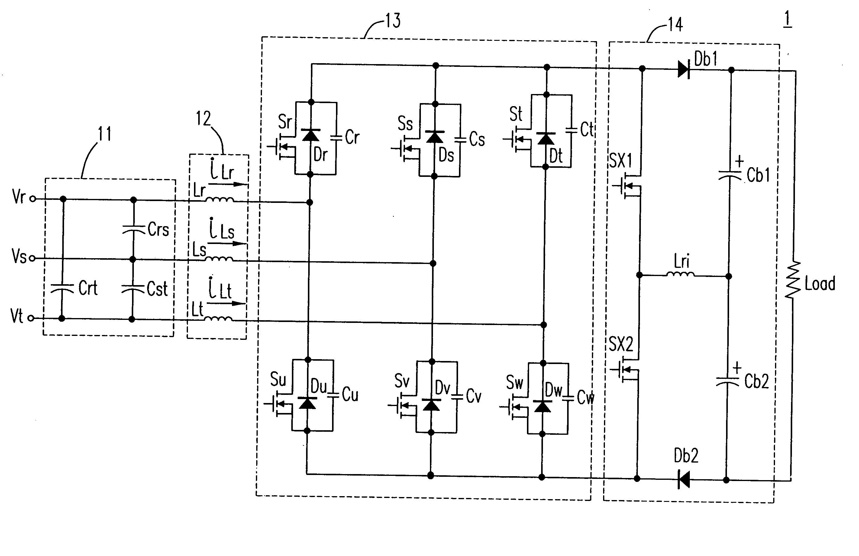
[0028] Please refer to FIG. 3, it shows the schematic circuit diagram of the first preferred embodiment of the three-phase power factor correction converter of the present invention 1 which includes a filter circuit 11, a plurality of boost inductors 12, a plurality of half-bridge switching devices 13 (each having a upper main switch module and a lower main switch module), and a soft-switching cell 14 (including a plurality of auxiliary switching devices each having an upper auxiliary switch and a lower auxiliary switch, a plurality of resonant inductors, a plurality of output capacitors, and a first and a second diodes). In which, the proposed converter 1 includes: three boost inductors Lr, Ls, and Lt, three filter capacitors Crs, Cst, and Crt (for filtering the high frequency harmonics inputted through the commercial power supply), six main switch modules Sr, Ss, St, Su, Sv, and Sw, two auxiliary switches Sx1 and Sx2, a resonant inductor Lri, two main diodes Db1 and Db2 (rectifyin...


PUM


Abstract

The proposed converter includes: three boost inductors, three filter capacitors, six main switch modules each having a switch element, a diode and a resonant capacitor, two auxiliary switches, two main diodes, a resonant inductor, and two output capacitors. A control circuit is employed for generating driving signals from six SPWM signals to drive the six main switches and the two auxiliary switches of the converter. A six-step control method is employed to adjust the SPWM signals and a soft-switching method is employed to generate the driving signals to turn on / off the six main switch modules and the two auxiliary switches when the voltage on the second terminal of each main switch module / auxiliary switch is zero and the current flows into each auxiliary switch is zero to correct the power factor.

Description

FIELD OF THE INVENTION [0001] The present invention relates to a three-phase power factor correction converter. More specifically, this invention relates to a soft-switching three-phase power factor correction converter. BACKGROUND OF THE INVENTION [0002] Please refer to FIG. 1, it shows the schematic circuit diagram of a traditional three-phase power factor correction converter of the prior art. In which, the three-phase power factor correction converter includes three filter capacitors Crt, Crs, and Cst, three boost inductors Lr, Ls, and Lt, six diodes Dr, Ds, Dt, Du, Dv, and Dw, and an output capacitor Cb. Although this apparatus has the advantage of having a relatively simple configuration, but the power factor of such an apparatus could only reach the highest value of around 0.93. Besides, the inductors of the above-mentioned apparatus, made of silicon steel, are relatively heavier and larger. Due to the aforementioned drawbacks, the passive power factor correction method emplo...

Claims


Application Information

Patent Timeline
Patent Type & Authority Applications(United States)
IPC IPC(8): H02M1/00H02M1/42
CPCY02B70/126H02M1/4216Y02B70/10Y02P80/10
Inventor CHANG, YU-MING
Owner DELTA ELECTRONICS INC
Why Eureka
Try Eureka