Highly efficient, high current drive, multi-phase voltage multiplier

a multi-phase voltage multiplier and high current drive technology, applied in the field of integrated circuits, can solve the problems of increasing capacitance, large buffers needed to drive these capacitors, and non-ideality of inverters, so as to reduce inefficiency, increase multiplier efficiency, reduce inefficiency

Inactive Publication Date: 2005-02-03
LSI CORPORATION
View PDF13 Cites 33 Cited by
  • Summary
  • Abstract
  • Description
  • Claims
  • Application Information

AI Technical Summary

Benefits of technology

[0007] The circuit of the present invention solves the problems associated with high load current voltage multiplier circuits. The circuit reduces the inefficiency due to the active level overlapping portion of the clock at high frequencies. It reduces the inefficiency due to extremely large drive currents on the inverters supplying current to the multiplying capacitors C1(*) and C2(*). It increases the efficiency of

Problems solved by technology

There are two problems associated with adding more capacitance in conventional voltage multiplier circuits.
One problem is that the buffers needed to drive these capacitors become very large.
The reason for this is the non-ideality of the inverters and their increasing ON resistance as the voltage at their outputs nears VDD or VSS.
Therefore, increasing the capacitor size to increase output drive will begin to lower the multiplier's efficiency and, at some point, the inefficiency of the multiplier will limit the design.
The second problem intro

Method used


Image

  • Highly efficient, high current drive, multi-phase voltage multiplier
  • Highly efficient, high current drive, multi-phase voltage multiplier
  • Highly efficient, high current drive, multi-phase voltage multiplier

Examples


Embodiment Construction

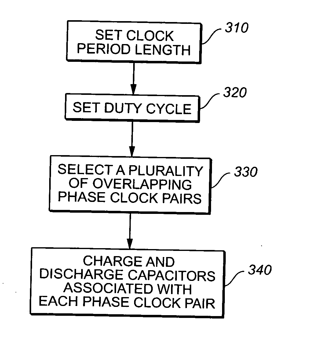
[0014] Reference will now be made in detail to the presently preferred embodiments of the invention, examples of which are illustrated in the accompanying drawings.

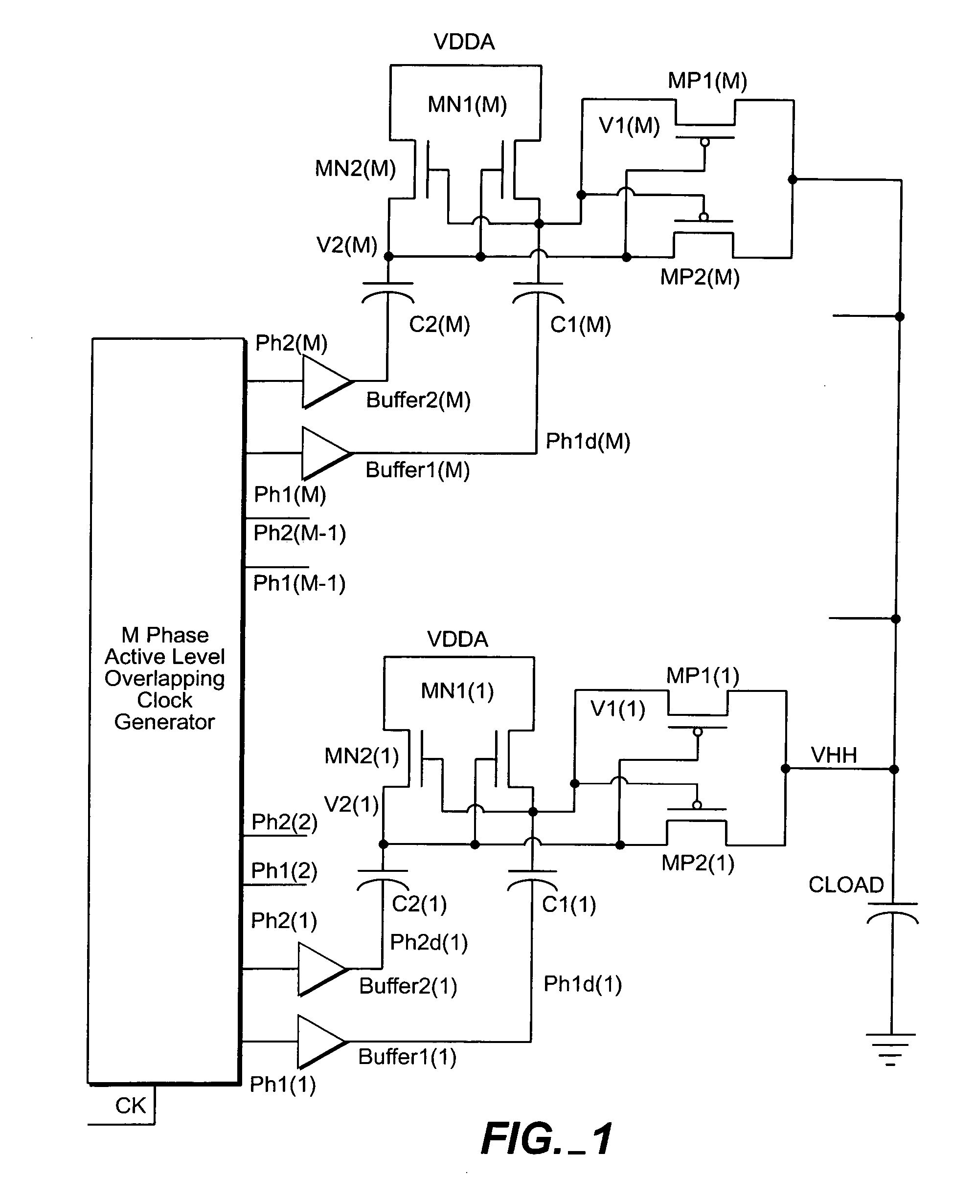
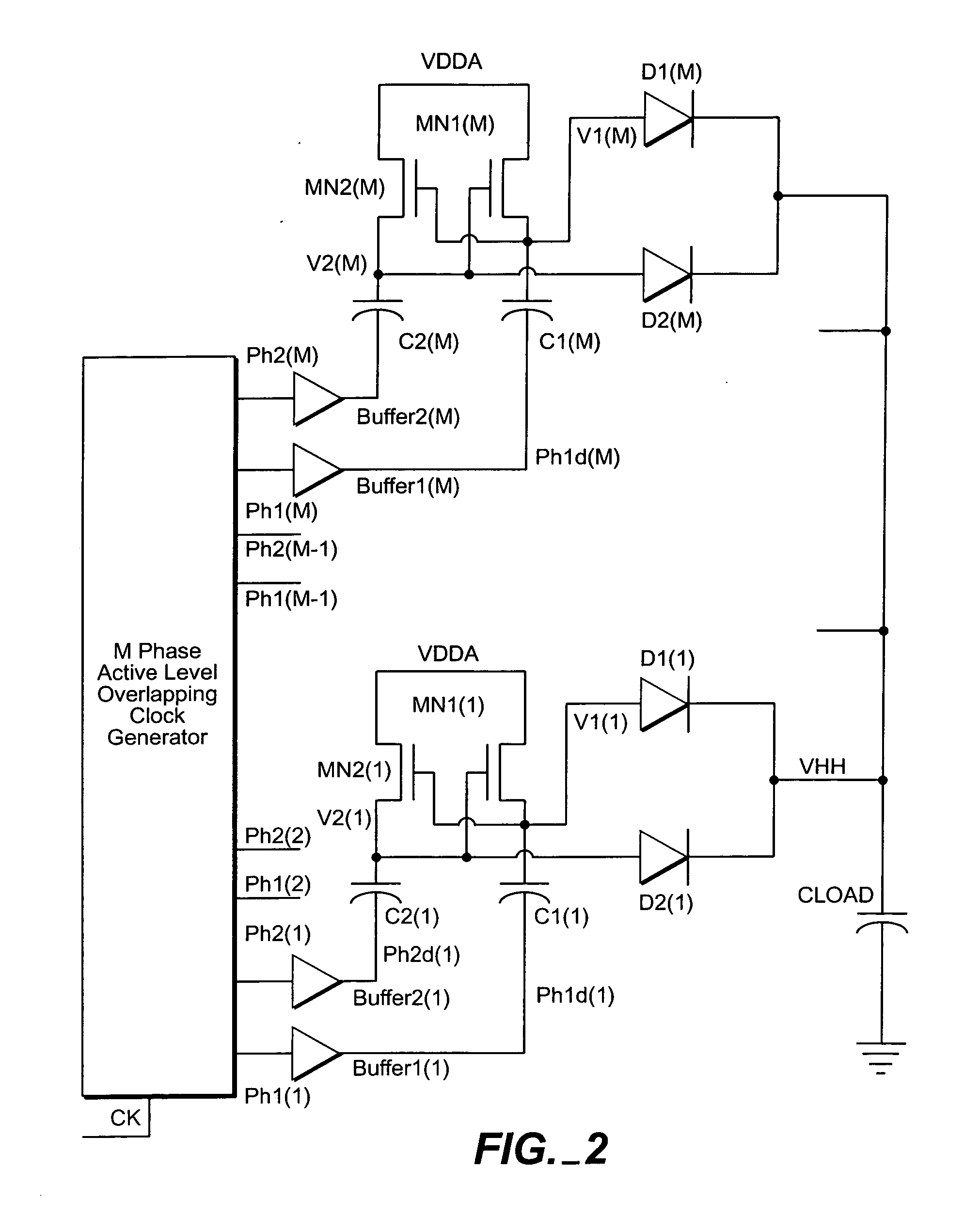
[0015] The present invention relates to a circuit and method for a high current, high frequency voltage multiplier. In the present invention, parallel circuit combinations perform a twice per phase clock charge pump and dump onto the voltage multiplier output line. Multiple parallel circuit combinations, each slightly out of phase with the others, ensure that the multiplier output continually has available a sufficient amount of charge for a driving current. Each parallel circuit combination includes two voltage dividers and two charging capacitors. The voltage dividers are formed from active or passive elements tied together: one end is fed through the power supply, the middle controls charging and discharging, and the other end provides the multiplied voltage.

[0016] The voltage multiplier of the present invention uses...


PUM


Abstract

The highly efficient, high current drive, multi-phase voltage multiplier reduces the inefficiency due to the active level overlapping portion of the clock at high frequencies, reduces the inefficiency due to extremely large drive currents on the inverters supplying current to the multiplying capacitors C1(*) and C2(*), and increases the efficiency of the multiplier by allowing M-1 phases to charge the output at any given time and providing more time given to each capacitor to fully charge and discharge. The ripple on the output is much smaller than in a single dual phase multiplier. This multi-phase voltage multiplier supplies very large current to the load while remaining very efficient.

Description

FIELD OF THE INVENTION [0001] The present invention generally relates to the field of integrated circuits, and particularly to a voltage doubling and voltage regulating integrated circuit. BACKGROUND OF THE INVENTION [0002] Voltage multipliers are used in various applications where a device or circuit, such as an integrated circuit, requires a higher voltage than that provided by the power supply. The voltage multiplier can only supply up to a certain rated current that is less than the power supply maximum current. During each clock cycle, enough charge must be moved from the doubling capacitors to the load capacitors to support the maximum rated current for an entire clock cycle until the next pulse of charge is delivered to the load. To increase the amount of load current the multiplier can supply, the designer generally can either add capacitance or increase the clock frequency (thereby increasing the number of times per second the charge is deposited on the load). There are two...

Claims


Application Information

Patent Timeline
IPC IPC(8): H02M3/07
CPCH02M3/073H02M2003/077H02M2003/075H02M3/075H02M3/077
Inventor MCNITT, JOHN L.RADKE, RUSSELL E.
Owner LSI CORPORATION
Why Eureka
Try Eureka