Quasi-three-dimensional method and apparatus to detect and localize interaction of user-object and virtual transfer device

Inactive Publication Date: 2005-02-03
TOMASI CARLO +1
View PDF19 Cites 127 Cited by
  • Summary
  • Abstract
  • Description
  • Claims
  • Application Information

AI Technical Summary

Benefits of technology

[0009] In a so-called structured-light embodiment, the invention includes a first optical system (OS1) that generates a plane of optical energy defining a fanbeam of beam angle φ parallel to and a small stand-off distance ΔY above the work surface whereon the virtual input device may be defined. In this embodiment, the plane of interest is the plane of light produced by OS1, typically a laser or LED light generator. The two parallel planes may typically be horizontal, but they may be disposed vertically or at any other angle that may be convenient. The invention further includes a second optical system (OS2) that is responsive to optical energy of the same wavelength as emitted by OS1. Preferably OS2 is disposed above OS1 and angled with offset θ, relative to the fan-beam plane, toward the region where the virtual input device is defined. OS2 is responsive to energy emitted by OS1, but the wavelength of the optical energy need not be visible to humans. The invention may also be implemented using non-structured-light configurations that may be active or passive. In a passive tr

Problems solved by technology

For example, although computers can now be implemented in almost pocket-size, inputting data or commands on a mini-keyboard can be time consuming and error prone.
While many cellular telephones can today handle e-mail communication, actually inputting messages using the small telephone touch pad can be difficult.
For example, a PDA has much of the functionality of a computer but suffers from a tiny or non-existent keyboard.
The challenge is how to detect or sense where the user's fingers or a stylus are relative to the virtual device.
Such optical systems rely upon luminance

Method used


Image

  • Quasi-three-dimensional method and apparatus to detect and localize interaction of user-object and virtual transfer device
  • Quasi-three-dimensional method and apparatus to detect and localize interaction of user-object and virtual transfer device
  • Quasi-three-dimensional method and apparatus to detect and localize interaction of user-object and virtual transfer device

Examples


Embodiment Construction

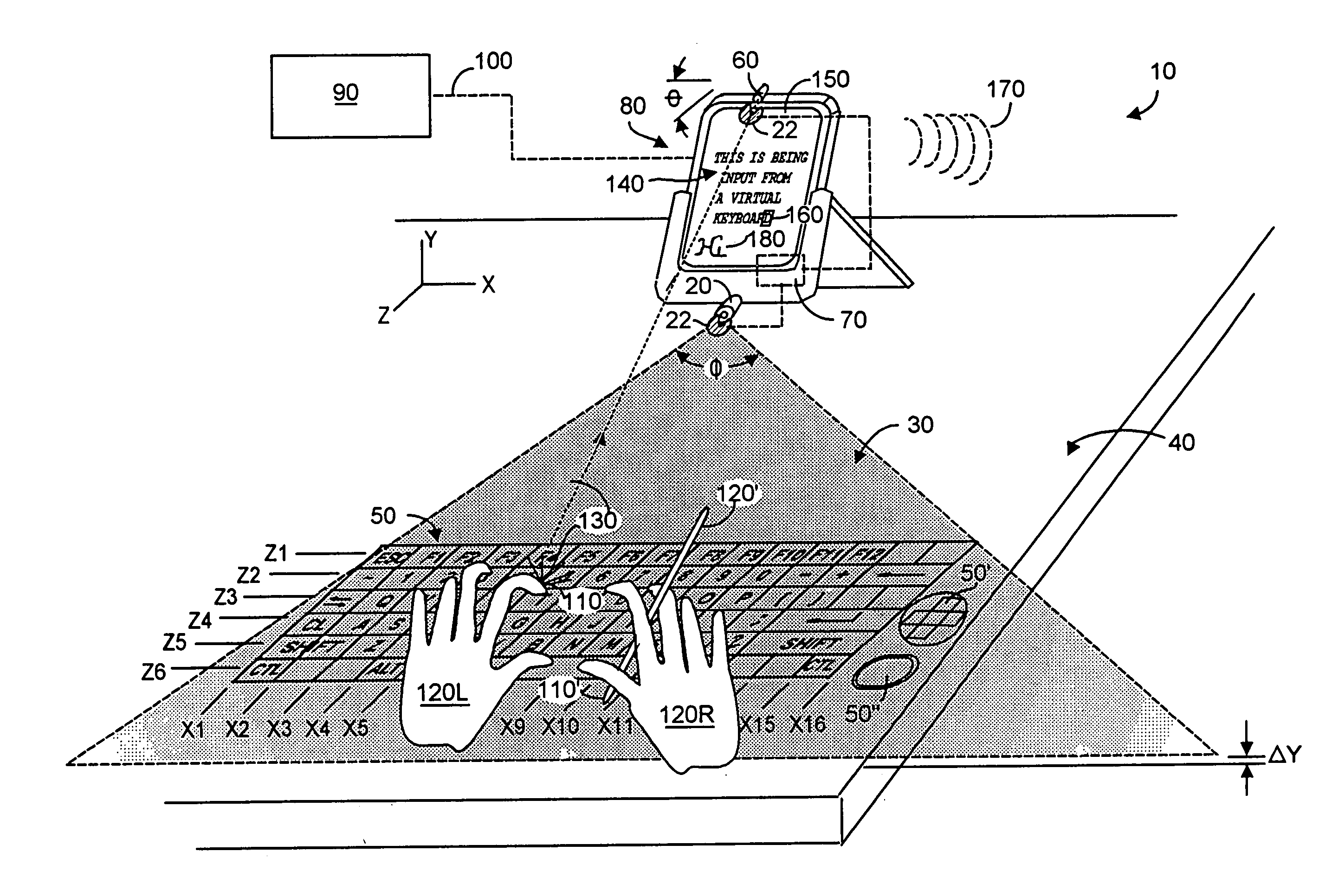
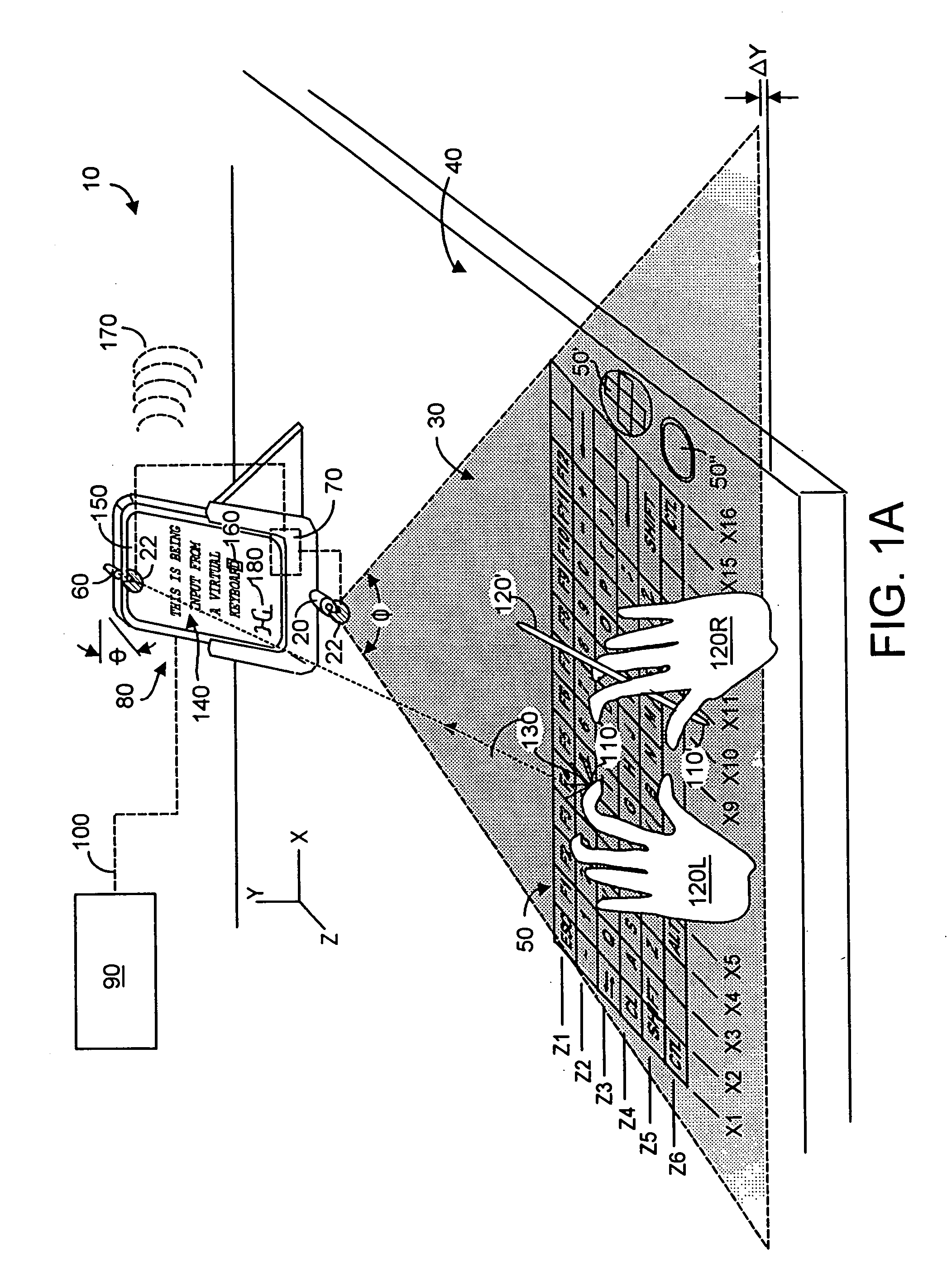
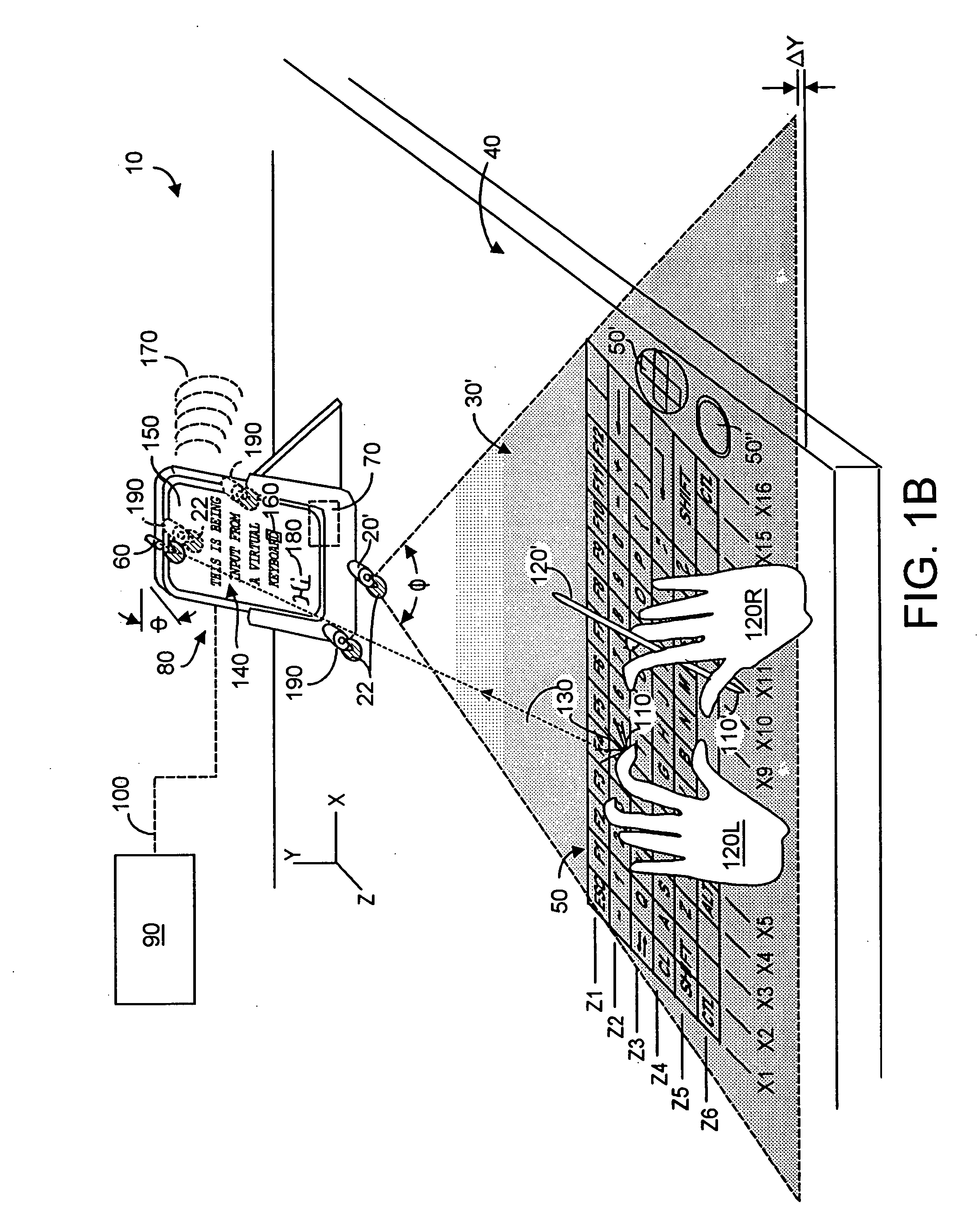
[0027]FIG. 1A depicts a preferred embodiment of a quasi-planar three-dimensional sensing system 10 comprising, in a structured-light system embodiment, a first optical system (OS1) 20 that emits a fan-beam plane 30 of optical energy parallel to a planar work surface 40 upon which there is defined a virtual input device 50 and / or 50′ and / or 50″. Preferably the fan-beam defines a fan angle φ, and is spaced-apart from the work surface by a-small stand-off distance ΔY. Any object (e.g., a user finger or stylus) attempting to touch the work surface must first contact the fan-beam and will thereby be illuminated (visibly or not visibly) with emitted optical energy. While fan-beam plane 30 and the work surface plane 40 are shown horizontally disposed in FIG. 1A, these two planes may be disposed vertically or indeed at any other angle that may be desired for a system. Note that, without limitation, work surface 40 could be a portion of a work desk, a table top, a portion of a vehicle, e.g.,...


PUM


Abstract

A system used with a virtual device inputs or transfers information to a companion device, and includes two optical systems OS1, OS2. In a structured-light embodiment, OS1 emits a fan beam plane of optical energy parallel to and above the virtual device. When a user-object penetrates the beam plane of interest, OS2 registers the event. Triangulation methods can locate the virtual contact, and transfer user-intended information to the companion system. In a non-structured active light embodiment, OS1 is preferably a digital camera whose field of view defines the plane of interest, which is illuminated by an active source of optical energy. Preferably the active source, OS1, and OS2 operate synchronously to reduce effects of ambient light. A non-structured passive light embodiment is similar except the source of optical energy is ambient light. A subtraction technique preferably enhances the signal/noise ratio. The companion device may in fact house the present invention.

Description

RELATION TO PREVIOUSLY FILED APPLICATION [0001] Priority is claimed from applicants' co-pending U.S. provisional patent application Ser. No. 60 / 287,115 filed on 27 Apr. 2001 entitled “Input Methods Using Planar Range Sensors”, from co-pending U.S. Provisional patent application Ser. No. 60 / 272,120 filed on 27 Feb. 2001 entitled “Vertical Triangulation System for a Virtual Touch-Sensitive Surface”, and from co-pending U.S. provisional patent application Ser. No. 60 / 231,184 filed on 7 Sep. 2000 entitled “Application of Image Processing Techniques for a Virtual Keyboard System”. Further, this application is a continuation-in-part from co-pending U.S. patent application Ser. No. 09 / 502,499 filed on 11 Feb. 2000 entitled “Method And Apparatus for Entering Data Using A Virtual Input Device”. Each of said applications is incorporated herein by reference.FIELD OF THE INVENTION [0002] The invention relates generally to sensing proximity of a stylus or user finger relative to a device to inpu...

Claims


Application Information

Patent Timeline
IPC IPC(8): G06F1/16G06F3/00G06F3/01G06F3/02G06F3/033G06F3/042
CPCG06F1/1613G06F1/1626G06F1/1632G06F1/1673G06K9/224G06F3/0221G06F3/0423G06F3/0426G06F3/04886G06F3/011G06V30/228
Inventor TOMASI, CARLORAFII, ABBAS
Owner TOMASI CARLO
Why Eureka
Try Eureka