
Progressive meter system architecture and method

Inactive Publication Date: 2005-02-03
MATHIS RICHARD M
View PDF10 Cites 15 Cited by
  • Summary
  • Abstract
  • Description
  • Claims
  • Application Information

AI Technical Summary

Benefits of technology

[0006] To address one or more aforementioned drawbacks and disadvantages of conventional gaming systems, a system of constructing a link progressive controller network is disclosed. An advantage of this system is to increase participation and generation of additional excitement for progressive type games. Another advantage of the present invention is that loss of stored data is either eliminated or reduced to a minimum since no central or master controller is needed. Further, the security risk of having just one point of entry to compromise the system is eliminated. Each monitor (gaming device or connectable to a gaming device) contains in computer data memory the entire status of the connected network. The present system includes provision of a bonus game that may be played upon an individual gaming apparatus or upon a link progressive network.
[0007] In one aspect of the present invention, a progressive gaming system is provided. The progressive gaming system includes a first gaming device having an input device, a display and a controller. The first gaming device can receive a wager from a first player to initiate a progressive type game. The progressive gaming system also has a second gaming device having an input device, a display and a controller. Here, the second gaming device is connected to the first gaming device via a communication link. The communication link may be wireless, wired, e.g., RS232, Internet or other type connectivity capable of allowing data transmission and receipt between two points.
[0008] The second gaming device can also receive a wager from a second player to initiate a progressive type game. Upon initiation of gaming, the first and second gaming devices exchange, with each other, information associated with the amount of wagers placed by the first and the second player on each respective gaming device by exchanging an electronic data packet of a predetermined format, in order to determine the total jackpot amount to be won. The determination of the total jackpot amount to be paid to the first player is performed by the controller of the first gaming device. Similarly, determination of the total jackpot amount to be paid to the second player is performed independently of the first gaming device by the controller of the second gaming device. Communication between the first and second gaming devices as to total amount available for pay to players is accomplished through the exchange of a data packet after which either gaming device may make a calculation as to amount to be paid according to predetermined parameters.
[0009] A further understanding of the nature and advantages of the present invention herein may be realized by reference to the remaining portions of the specification and the attached drawings. References to “steps” of the present invention should not be construed as limited to “step plus function” means, and are not intended to refer to a specific order for implementing the invention. Further features and advantages of the present invention, as well as the structure and operation of various embodiments of the present invention, are described in detail below with respect to the accompanying drawings. In the drawings, the same reference numbers indicate identical or functionally similar elements.

Problems solved by technology

It is known that administrators of such conventional progressive systems have encountered difficulty in retrieving centrally stored data to accomplish proper functioning of the gaming system.
This situation can occur, for example, when stored data becomes corrupt or becomes lost for any number of reasons; accordingly, multiple copies of data reside upon the central controller and are checked against each other frequently.
Nevertheless, it is believed that such conventional gaming systems were popular not only because controller costs were generally high but also due to the increased complexity required to implement decentralized processing systems.
Consequently, display of a progressive jackpot available for win that is not correct (larger than actual value) can result in a large loss for an operator of gaming machines since many gaming jurisdictions will require that it be paid if won before the amount displayed can be adjusted downward.

Method used


Image

  • Progressive meter system architecture and method
  • Progressive meter system architecture and method
  • Progressive meter system architecture and method

Examples


Embodiment Construction

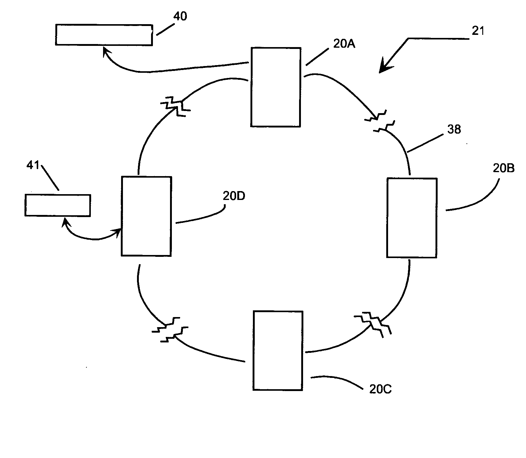
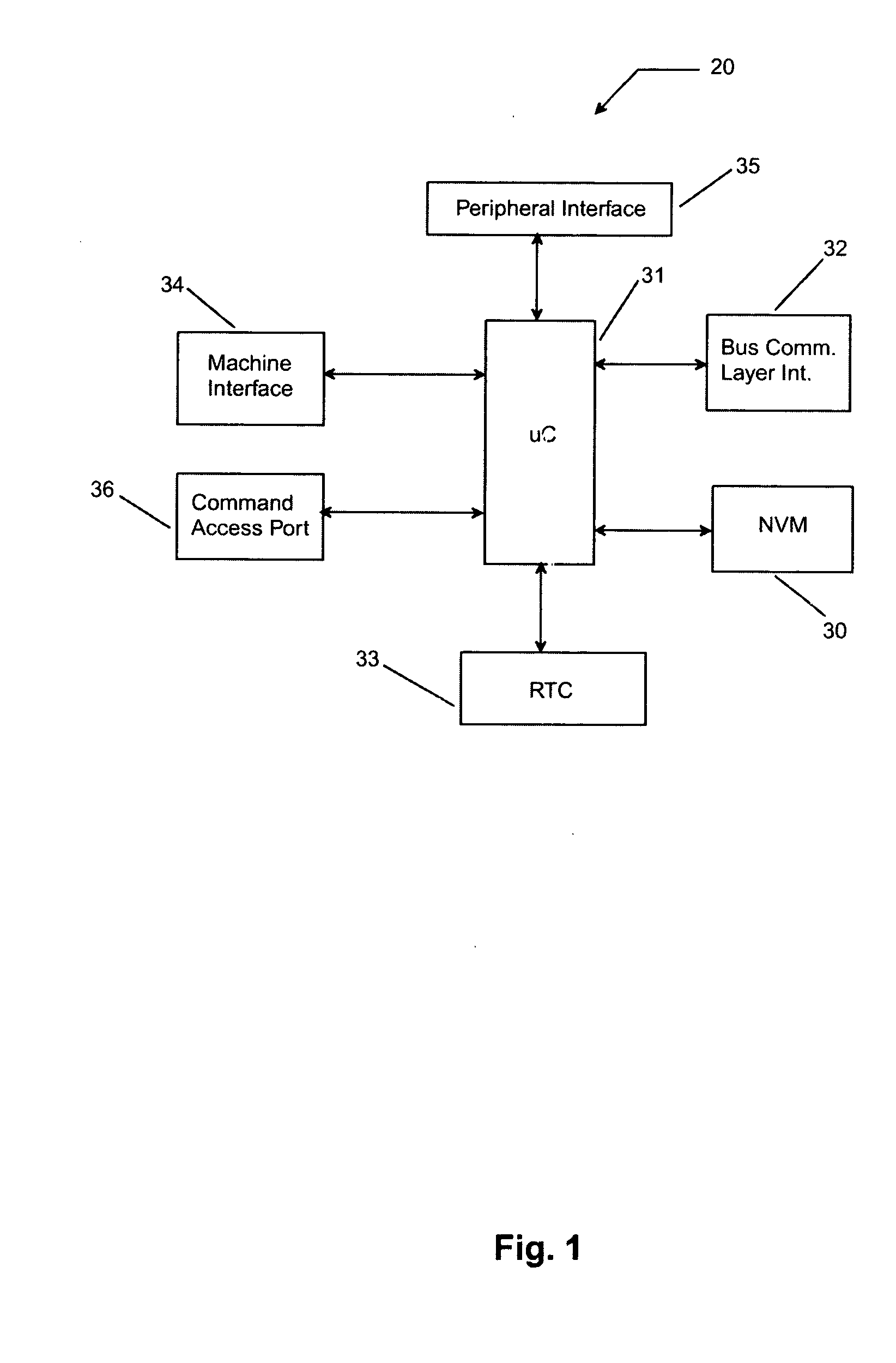
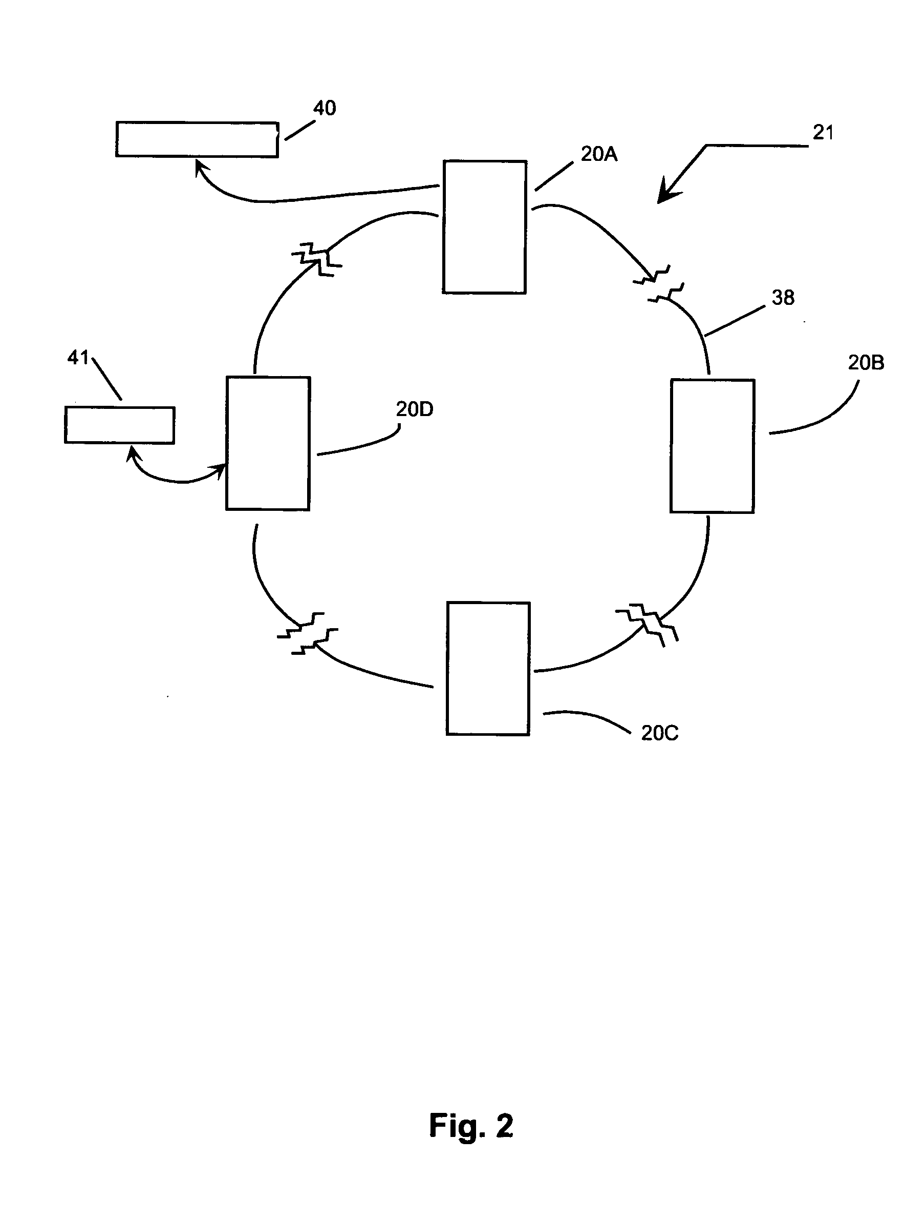
[0017] The present invention in the form of one or more exemplary embodiments will now be described. Consider a link progressive system that connects a plurality of monitors of gaming devices via a communication bus. The communication bus may comprise a physical wire connection or may comprise wireless means such as radio frequency (RF), infrared (IR). The monitors of gaming devices may be a device separate from a gaming apparatus or may be integrated into and be a part of the gaming apparatus. Each monitor is an intelligent device and comprises a unit for communicating with the gaming apparatus to which it is attached, a unit for decision making based upon calculated or predetermined conditions, a unit for communicating with other monitors to which it may be connected and a unit for communicating with peripherals that may be attached to enhance its function.

[0018] A block diagram of a monitor of a gaming device as described in the present invention may be as shown in FIG. 1. The m...


PUM


Abstract

A method of constructing a link progressive meter system to increase participation and generate additional player excitement during a progressive type game. Each interface or monitor to a gaming machine or monitored point can act and process decisions independently of other monitors. Each monitor contains in computer data memory the status of the entire network and this is replicated throughout the entire network. A method for a bonus game that may be implemented upon an individual gaming apparatus or upon a link progressive network connecting a plurality of gaming machines is described.

Description

CROSS REFERENCE TO RELATED APPLICATIONS [0001] The present application is based on and claims priority from provisional application, Application No. 60 / 400,299, entitled Progressive Meter System Architecture and Method, filed Jul. 31, 2002.BACKGROUND OF THE INVENTION [0002] The present invention is related generally to casino gaming systems and more specifically to casino gaming progressive meter systems and methods. Conventional progressive gaming systems are generally known in which multiple gaming devices are interconnected and bonus games and / or an incrementally varying jackpot amount based on a percentage of total amounts played can be won. Generally, the gaming devices report coin-in and game-win information, which enable jackpot increments to be generated for transmission back to the gaming devices. While progressive gaming systems have proved successful, the prospect for increased participation by current or additional players and increased generation of excitement continue ...

Claims


Application Information

Patent Timeline
IPC IPC(8): A63F13/00G07F17/32
CPCG07F17/3258G07F17/32
Inventor MATHIS, RICHARD M.
Owner MATHIS RICHARD M
Features
  • Generate Ideas
  • Intellectual Property
  • Life Sciences
  • Materials
  • Tech Scout
  • Unparalleled Data Quality
  • Higher Quality Content
  • 60% Fewer Hallucinations
Learn More