Inflatable nuclear prosthesis

a technology of intervertebral discs and prostheses, applied in the field of orthopaedic surgery, can solve the problems of reducing the height and mobility of the disc space, reducing the normal stress of the disc, and loosing the surrounding support ligaments of the spine, so as to reduce or eliminate abnormal stresses, restore sufficient disc space, and reduce the effect of stress

Active Publication Date: 2005-02-03
SUDDABY LOUBERT
View PDF8 Cites 150 Cited by
  • Summary
  • Abstract
  • Description
  • Claims
  • Application Information

AI Technical Summary

Benefits of technology

[0012] An object of the invention is provide an intervertebral disc nuclear replacement prosthesis that simultaneously restores sufficient disc spac

Problems solved by technology

The effect of this deterioration is a loss of water content of the gel matrix of the nucleus and a concomitant compacting of its fibers with a resultant loss of disc space height which in turn causes a loosening of the surrounding support ligaments of the spine and the development of what is termed degenerative instability.
This instability results in a pathologic excess of movement at the intervertebral disc space that further accentuates the degeneration of both the nucleus and the annulus of the disc.
This bulging of the annulus or protrusion of the nucleus can compress nerves and cause disabling sciatic pain.
Distension or bulging of the annulus alone is frequently sufficient to produce disabling back pain because of compression or inflammation of free nerve endings present in the outer annulus of the disc.
This in turn accelerates degeneration of the nei

Method used


Image

  • Inflatable nuclear prosthesis
  • Inflatable nuclear prosthesis
  • Inflatable nuclear prosthesis

Examples


first embodiment

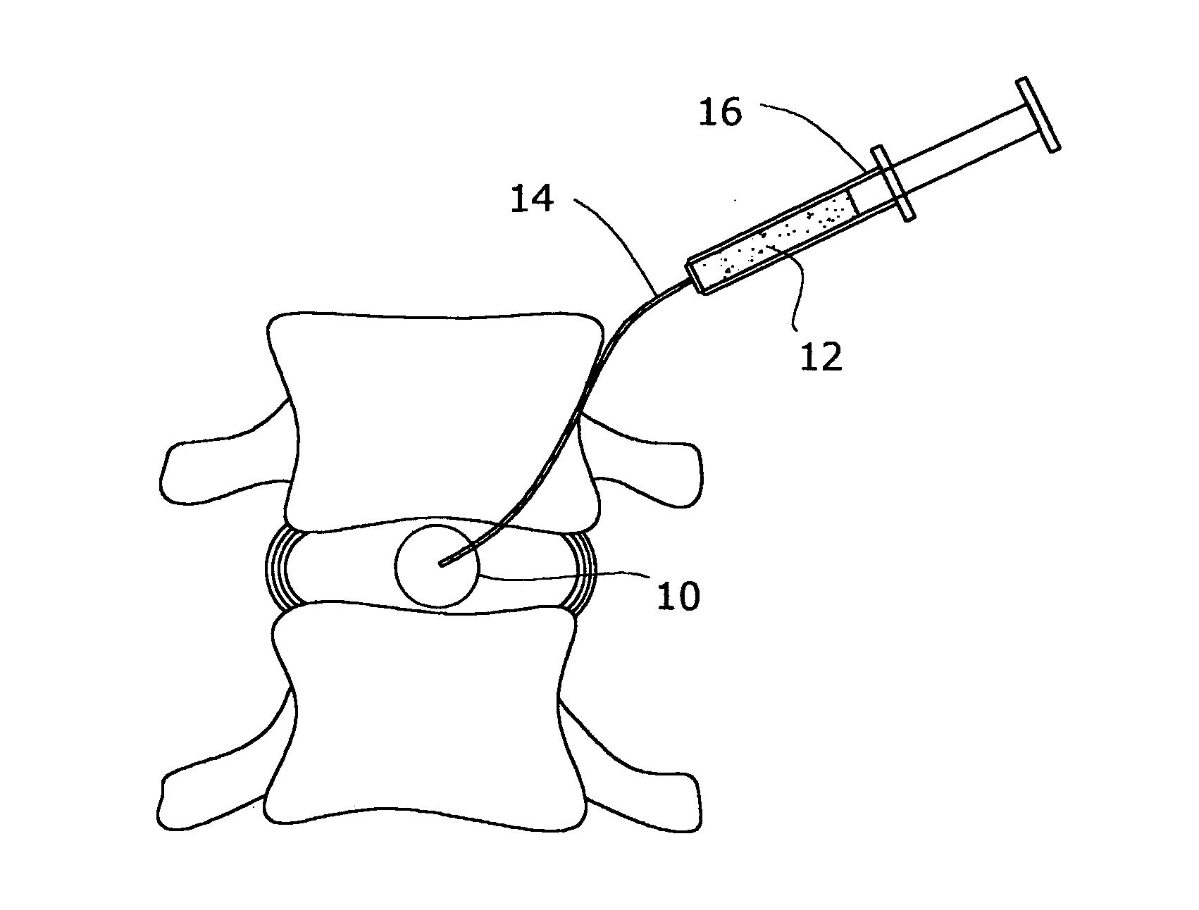
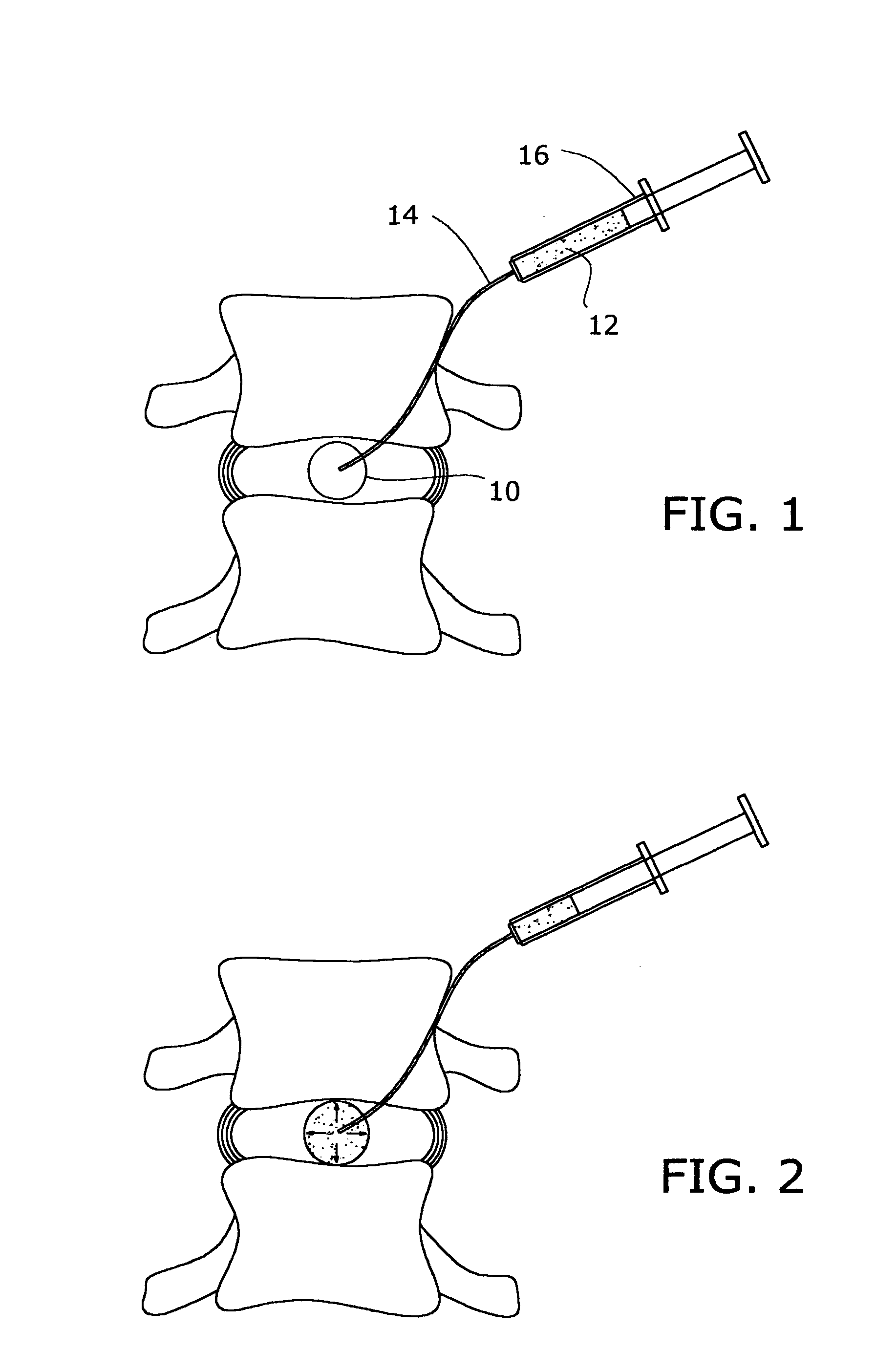
[0029] In the invention, a deflated balloon 10 (FIG. 1) is placed within an intervertebral disc in which a cavity has been formed by a complete nuclectomy. The balloon is then inflated with a liquid contrast medium (not shown), while the area is observed by the surgeon, who terminates inflation when the desired distension is observed. Then the contrast medium is completely withdrawn, and the withdrawn volume is noted.

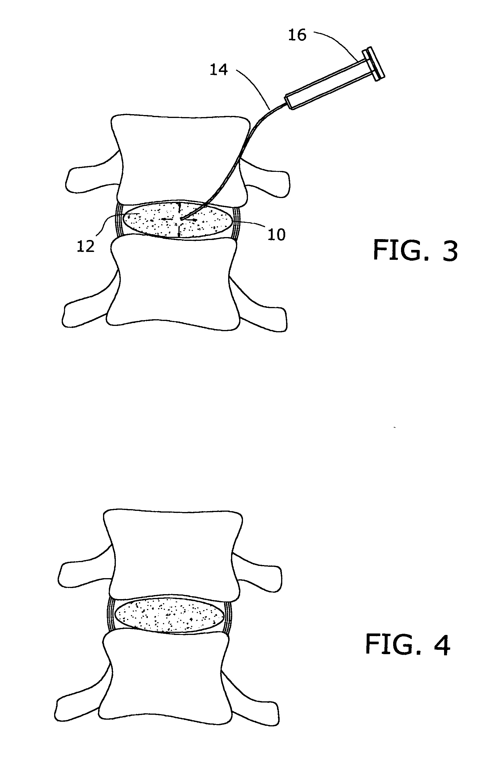
[0030] Next, an identical volume of a hardenable material 12 in liquid form is injected through a conduit 14 connected to a source of the material under pressure, for example a syringe 16. As material enters the balloon, the balloon expands as suggested by the arrows in FIGS. 2 and 3. Note that the annular fibers become more taut as the pressure increases the separation distance between the vertebrae.

[0031] Once the predetermined volume of the hardenable material has been injected, it is allowed or induced to harden. When the material has hard hardened at least to the ...

second embodiment

[0032] In the invention, two balloons, one inside the other, are inserted into the disc. Using volume measuring and filling techniques similar to those described above, the inner balloon 10 is filled with a first liquid material 12, and the chamber 18 formed between the inner balloon 10 and the outer balloon 20 is filled with a second hardenable material 22 in liquid form. The first liquid material 12 is preferably hardenable, but to a substantially lesser hardness that the outer material, so that cured construct is relatively soft on the inside, and relatively harder on the outside, like a natural disc. The inner portion thus retains greater elastic properties to provide a cushioning effect, whereas the outer portion has little or no elasticity, to preserve the strength and integrity of the entire construct.


PUM

PropertyMeasurementUnit
Volumeaaaaaaaaaa
Hardeningaaaaaaaaaa
Hardnessaaaaaaaaaa

Abstract

The nucleus of an intervertebral disc is replaced with a construct including a distendable sack or balloon which is inflated with a hardenable material and is detached in situ when the injected material has hardened. Alternatively, two nested balloons may be inserted, and then filled with materials which have different hardnesses when cured, to simulate a natural disc.

Description

BACKGROUND OF THE INVENTION [0001] This invention relates to orthopedic surgery, more particularly to a prosthetic nuclear replacement for a damaged intervertebral disc, and a surgical procedure for implanting the construct in the intervertebral disc space. [0002] The normal intervertebral disc has an outer fibrous ring, constituted mainly of collagen fibers, which strongly binds the vertebral elements together. This fibrous outer layer, or annulus, encircles a soft gel-like matrix, or nucleus, which serves both as a cushion and as a mobile and compressible element that allows motion to occur between the vertebral bodies above and below the intervertebral disc. This gel matrix is 95% water. The types of motion that can occur at the level of the intervertebral disc include flexion, extension, lateral bending and varying degrees of torsion or rotation. [0003] In the course of a day, the normal intervertebral disc may encounter various combinations of these bending or twisting motions ...

Claims


Application Information

Patent Timeline
IPC IPC(8): A61F2/00A61F2/30A61F2/44A61F2/46
CPCA61F2/441A61F2/442A61F2/4611A61F2002/30014A61F2002/30016A61F2002/30563A61F2250/0019A61F2002/30586A61F2002/444A61F2002/4627A61F2210/0085A61F2250/0018A61F2002/30583
Inventor SUDDABY, LOUBERT
Owner SUDDABY LOUBERT
Why Eureka
Try Eureka