

Method for changing glass compositions in melting installations, and corresponding melting installation
Patent Information
- Authority / Receiving Office
- US · United States
- Current Assignee / Owner
- SCHOTT AG
- Publication Date
- 2005-02-10
- Estimated Expiration
- Not applicable · inactive patent
Smart Images
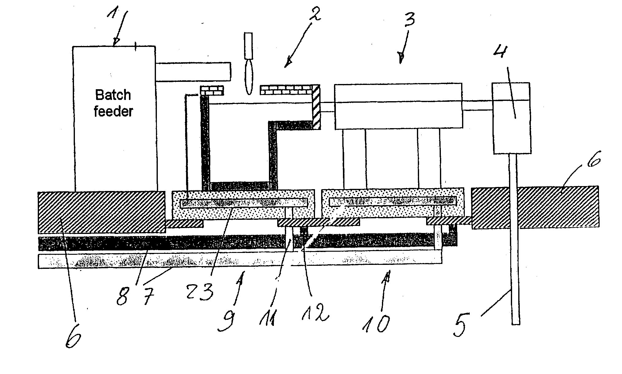
Figure 1 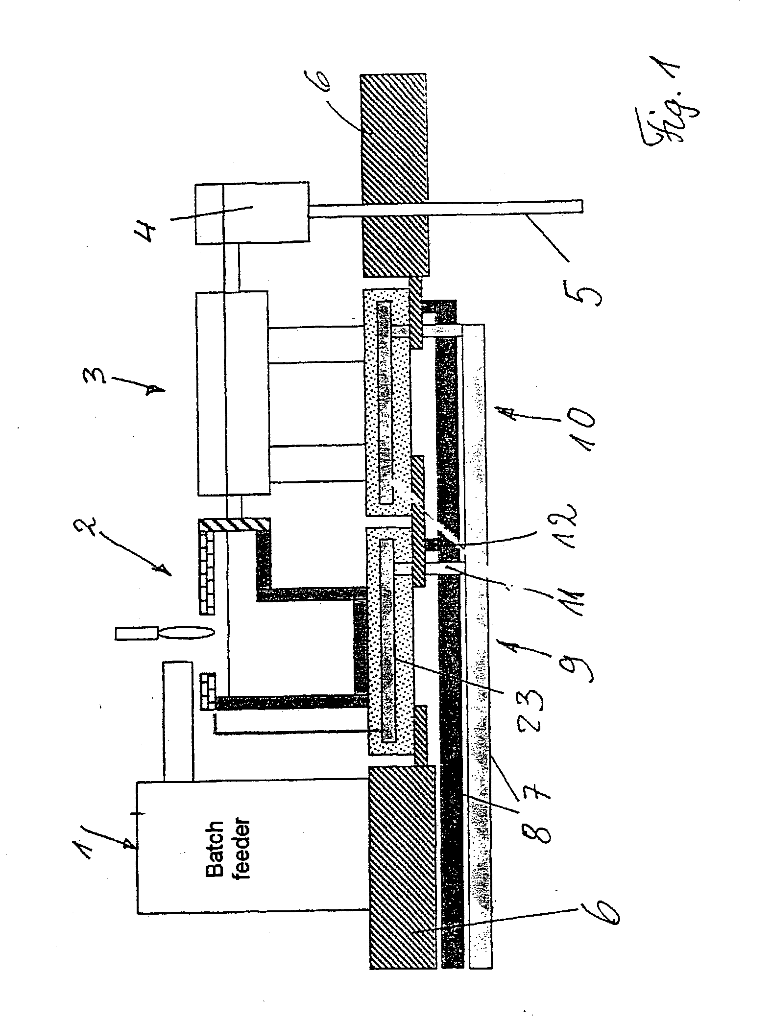
Figure 2 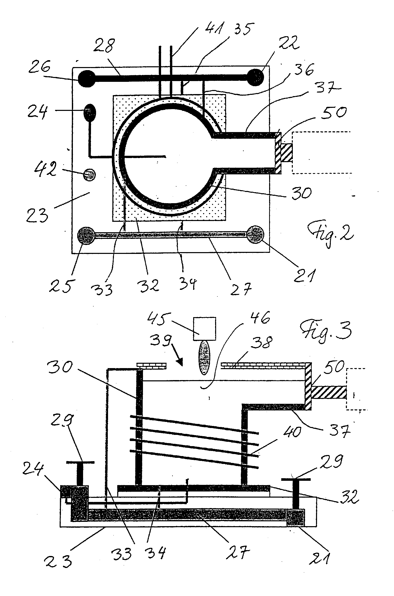
Figure 3
Abstract
Description
CROSS-REFERENCE TO RELATED APPLICATIONS
[0001] Not applicable. STATEMENT REGARDING FEDERALLY SPONSORED RESEARCH OR DEVELOPMENT
[0002] Not applicable. BACKGROUND OF THE INVENTION
[0003] The invention relates to a method for changing glass compositions in continuously operated melting installations, in particular for aggressive, high-purity and / or high-melting glasses, and to a melting installation which is suitably modified for this method.
[0004] Hitherto, it has been attempted as far as possible to melt each (special) glass which is to be produced in a separate melting installation. Given the very high number of different types of glasses and the widely differing quantities to be melted, the result is a large number of melting installations, each of which requires a corresponding “infrastructure”. Melting installations of this type are often not fully loaded.
[0005] It would inherently be less expensive to operate just a single melting installation for various types of glasses. Thi...