Sensor arrangement

a sensor and arrangement technology, applied in the field of sensor arrangement, can solve the problems of nm sensor electrodes being read individually, signal transmission, and the principle encountering its limits, and achieve the effects of improving the temporal resolution of the sensor arrangement, increasing sampling rate, and high susceptibility to interferen

Active Publication Date: 2005-02-10
INFINEON TECH AG
View PDF12 Cites 26 Cited by
  • Summary
  • Abstract
  • Description
  • Claims
  • Application Information

AI Technical Summary

Benefits of technology

[0018] Whereas in known realizations of sensor arrangements, all the sensor arrays are read successively and, therefore, nm signals are determnined in one cycle, only n+m signals are output and digitized in the realization according to the invention. Consequently, it is possible to achieve significantly increased sampling rates, i.e., a significantly improved temporal resolution of the sensor arrangement.
[0019] A further advantage is that a genuine snapshot of the potential conditions on the active sensor surface is possible. Whereas in the conventional case the matrix elements are read successively and are thus detected in a manner temporally staggered with respect to one another, the instantaneous situation can be “retained” and subsequently evaluated in the case of the invention. This results inter alia from the small nu

Problems solved by technology

In the case of a larger number of sensor arrays or decreasing distances between neighboring sensor arrays, this principle encounters its limits owing to the high space requirement of the high number of lines.
To summarize, sensor arrangements for the spatially resolved a

Method used


Image

  • Sensor arrangement
  • Sensor arrangement
  • Sensor arrangement

Examples


Embodiment Construction

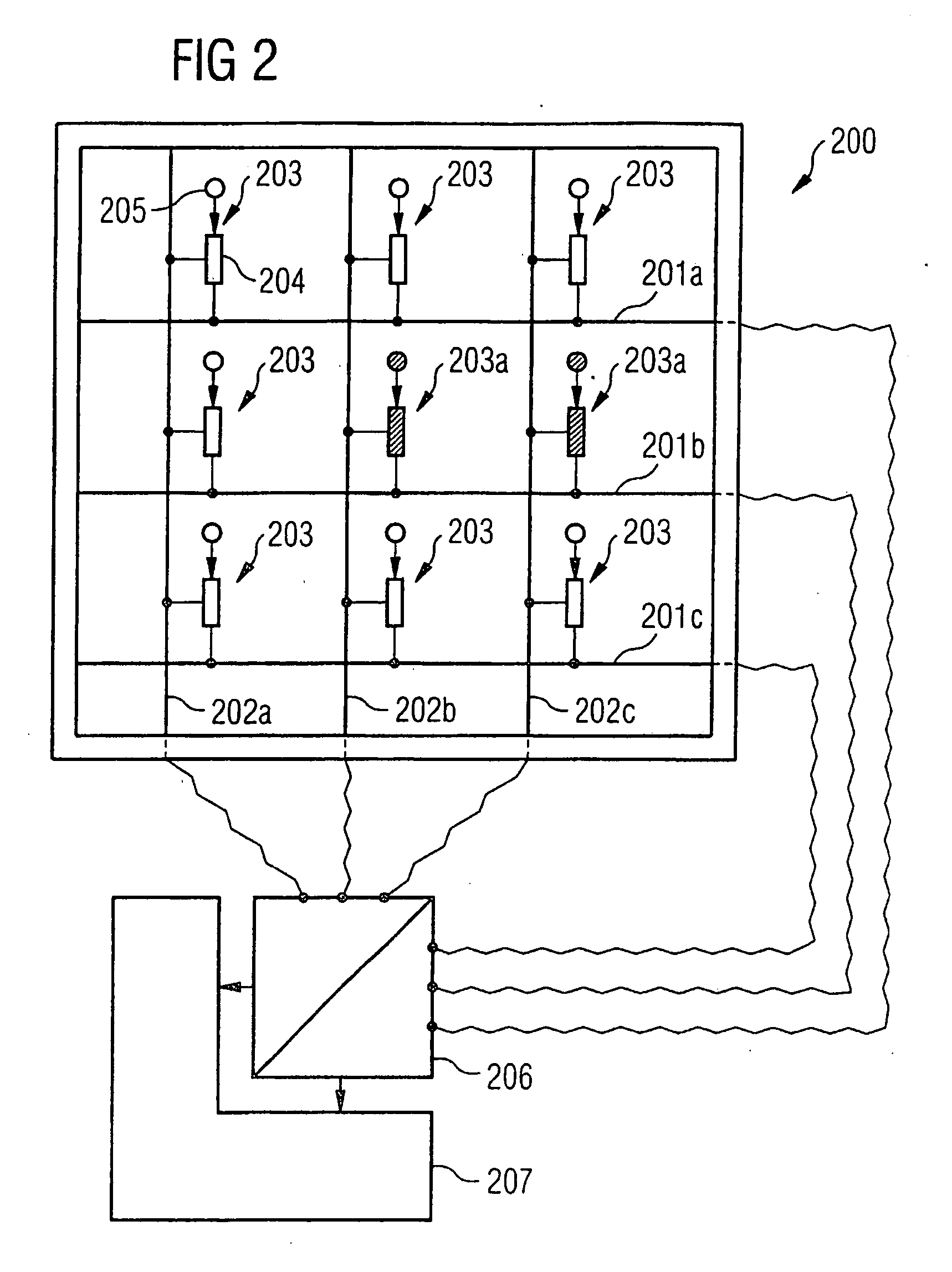
[0079] A description is given below, referring to FIG. 2, of a sensor arrangement in accordance with a first exemplary embodiment of the invention.

[0080] The sensor arrangement 200 shown in FIG. 2 has three row lines 201a, 201b, 201c arranged in a horizontal direction, three column lines 202a, 202b, 202c arranged in a vertical direction, and nine sensor arrays 203 arranged in the crossover regions between the three row lines 201a, 201b, 201c and column lines 202a, 202b, 202c, with a coupling device 204 for electrically coupling a respective row line 201a, 201b or 201c to a respective column line 202a, 202b or 202c and with a sensor element 205 assigned to the coupling device 204, the sensor element 205 being set up in such a way that the sensor element 205 influences the electric current flow through the assigned coupling device 204. Furthermore, the sensor arrangement 200 has a means 206 which is electrically coupled to a respective end section of the row lines 201a, 201b, 201c an...


PUM

PropertyMeasurementUnit
Angleaaaaaaaaaa
Angleaaaaaaaaaa
Flow rateaaaaaaaaaa

Abstract

Sensor arrangement having row and column lines arranged in first and second directions, respectively, sensor arrays arranged in crossover regions of the row and column lines, a detector, and a decoding device. The sensor arrays have a coupling device for electrically coupling respective row and column lines, and a sensor element to influence electric current flow through the coupling device. The detector is electrically coupled to a respective end section of at least a portion of the row and column lines, and detects a respective accumulative current flow from the individual electrical current flows provided by the sensor arrays of the respective lines. The decoding device is coupled to the row and column lines, and evaluates at least a portion of the accumulative electric current flows fed to the decoding device via the row and column lines to determine at which of the sensor elements a sensor signal is present.

Description

CROSS-REFERENCE TO RELATED APPLICATION [0001] This application is a continuation of International Patent Application Serial No. PCT / DE02 / 03098, filed Aug. 23, 2002, which published in German on May 8, 2003 as WO 03 / 038423 A2, and is incorporated herein by reference in its entirety.FIELD OF THE INVENTION [0002] The invention relates to a sensor arrangement. BACKGROUND OF THE INVENTION [0003] Present-day developments in many fields of science and technology are characterized by the fact that areas formerly independent of one another are increasingly being combined. One example of an interdisciplinary area is the interface between biology and semiconductor technology. A topic of present-day research is, by way of example, the economically very interesting coupling between biological cell assemblages (such as neurons, for example) and silicon microelectronics. [0004] In accordance with one concept, a biological system is grown on the surface of a semiconductor-technological sensor and i...

Claims


Application Information

Patent Timeline
IPC IPC(8): G01N27/414G01N33/487G06K9/00
CPCG01N27/4145G06K9/0002G01N33/4836G06V40/1306
Inventor EVERSMANN, BJORN-OLIVERPAULUS, CHRISTIANSTROMBERG, GUIDOTHEWES, ROLAND
Owner INFINEON TECH AG
Why Eureka
Try Eureka