LED drive circuit

Active Publication Date: 2005-02-10
LITE ON TECH CORP
View PDF6 Cites 40 Cited by
  • Summary
  • Abstract
  • Description
  • Claims
  • Application Information

AI Technical Summary

Benefits of technology

[0020] By means of the drive circuit of the present invention, it is possible to produce a negative feedback circuit, without using a current mirror for the structural elements that decrease operating speed or a differential amplifier that makes the circuit larger. Furthermore, by means of the LED drive circuit of the present inve

Problems solved by technology

By means of these circuits, the light-emitting diode is controlled by voltage and therefore, the circuits do not have a structure with which the light emission is precisely controlled and thus, they are not appropriate for use in high-performance optical communications.
However, control using a current mirror circuit cannot be applied in high-speed switching, and the use of PNP-type transistors that operate relatively slowly makes high-speed operation of the

Method used


Image

  • LED drive circuit
  • LED drive circuit
  • LED drive circuit

Examples


Example

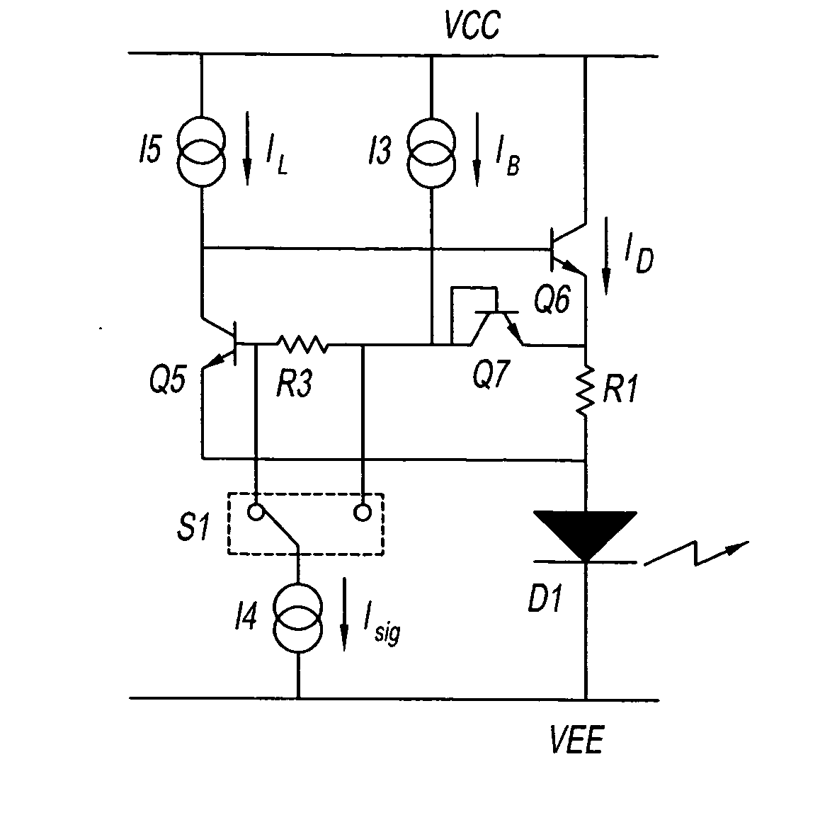
[0029] Preferred embodiments of the present invention will now be described while referring to the drawings. A schematic diagram showing an exemplary circuit structure of the LED drive circuit of the present invention is shown in FIG. 5.

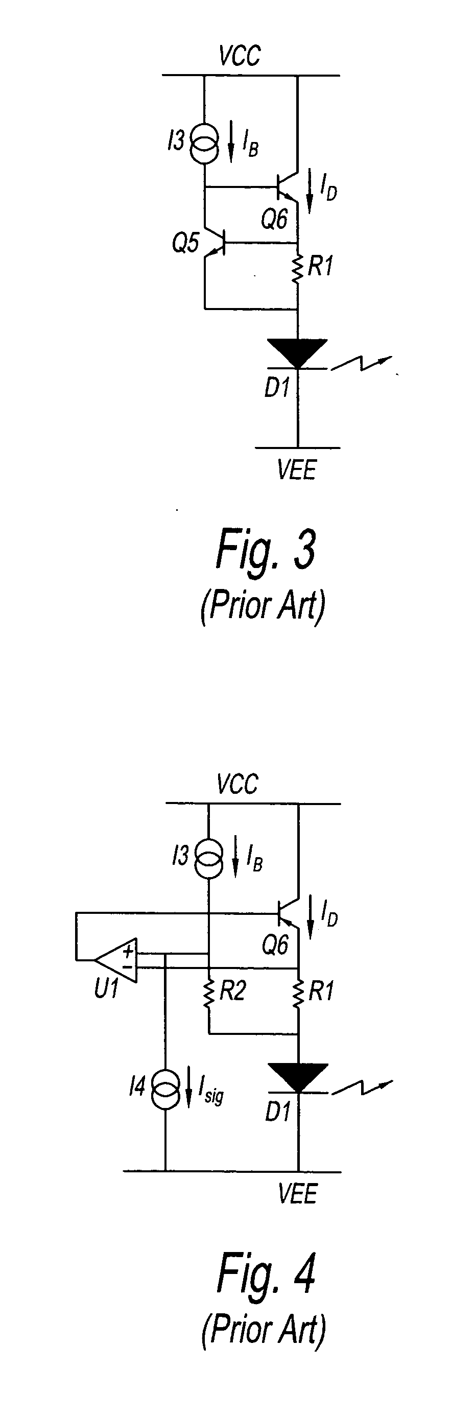
[0030]FIG. 5 can be compared with the circuit in FIG. 3. Attention should be focused on the fact that resistor R3 of the LED drive circuit provides a means of external control for the circuit. A pair of wires, one at each of the two terminals of R3, connect to a single-pole quadruple switch S1. Switch S1 functionality for determining whether or not control current I4 is being drawn from either of the two terminals of resistor R3 (that is, is flowing down). For instance, when the current is being drawn from the left side of resistor R3 in the figure, a voltage drop is produced by resistor R3, but if current is being drawn from the right side of resistor R3, a voltage drop is not produced. The voltage between the base emitters of transistor Q5 can be ...


PUM


Abstract

An LED drive circuit, wherein a circuit that drives light-emitting diode with a common connected cathode has a resistor connected to the anode of the light-emitting diode, an NPN-type transistor connected to the second terminal of the resistor that approximately determines the control current for the emission of light in cooperation with the resistor, an NPN-type transistor positioned in parallel with the resistor and connected to the anode of the light-emitting diode, and a current supply, a level shifter, and a switch for selectively changing the voltage between the base-emitter of the second transistor, which are placed between the base of transistor and resistor.

Description

FIELD OF THE INVENTION [0001] The present invention relates to a light-emitting diode (LED) constant-current drive circuit, and in particular, provides an LED drive circuit used in the application of optical communications that drives a light-emitting diode with a common cathode by current pulse. DISCUSSION OF THE BACKGROUND ART [0002] Light-emitting diodes are usually used as a light-emitting element in optical communications technology using optical fibers. The emitter-grounded or collector-grounded circuits in shown FIGS. 1(a) and (b) are referred to as the drive circuit for these types of LEDs. By means of these circuits, the light-emitting diode is controlled by voltage and therefore, the circuits do not have a structure with which the light emission is precisely controlled and thus, they are not appropriate for use in high-performance optical communications. That is, in high-performance optical communications control of the light emitted from a light-emitting diode should be p...

Claims


Application Information

Patent Timeline
IPC IPC(8): H01L27/15H01L33/00H05B37/00H05B44/00
CPCH05B33/0812Y02B20/345Y02B20/343Y02B20/30H05B45/397
Inventor YAMAMOTO, KENJISATOKATA, AKIHIKO
Owner LITE ON TECH CORP
Why Eureka
Try Eureka