Method and apparatus for efficient mixed signal processing in a digital amplifier

a digital amplifier and mixed signal technology, applied in the field of switching amplifiers, can solve the problems of increasing the efficiency of the amplifier, increasing the noise improvement achieved by increasing the osr, and ultimately limited, and achieves high efficiency, low impedance load, and high power accuracy of the input.

Inactive Publication Date: 2005-02-10
AVAGO TECH WIRELESS IP SINGAPORE PTE
View PDF19 Cites 14 Cited by
  • Summary
  • Abstract
  • Description
  • Claims
  • Application Information

AI Technical Summary

Benefits of technology

A system and method of creating a highly efficient digital amplifier which can take either analog or digital inputs, and produce a high power accurate representation of the input to drive speakers or other low impedance load is described. The system employs a transition detector and delay unit which allows the comparator of the signal modulator to ignore its inputs for a pre-determined number of subsequent clock cycles once an output transition has been detected. Through the use of faster clocks and variable clock cycle skips upon the comparator's output transition, finer resolution of the feedback's c

Problems solved by technology

The constant struggle in this field is to increase the efficiency of the amplifiers.
However, noise improvements achieved by increases in the OSR,

Method used


Image

  • Method and apparatus for efficient mixed signal processing in a digital amplifier
  • Method and apparatus for efficient mixed signal processing in a digital amplifier
  • Method and apparatus for efficient mixed signal processing in a digital amplifier

Examples


Embodiment Construction

The present description is of the best presently contemplated mode of carrying out the invention. This description is made for the purpose of illustrating the general principles of the invention and should not to be taken in a limiting sense. The scope of the invention is best determined by reference to the appended claims.

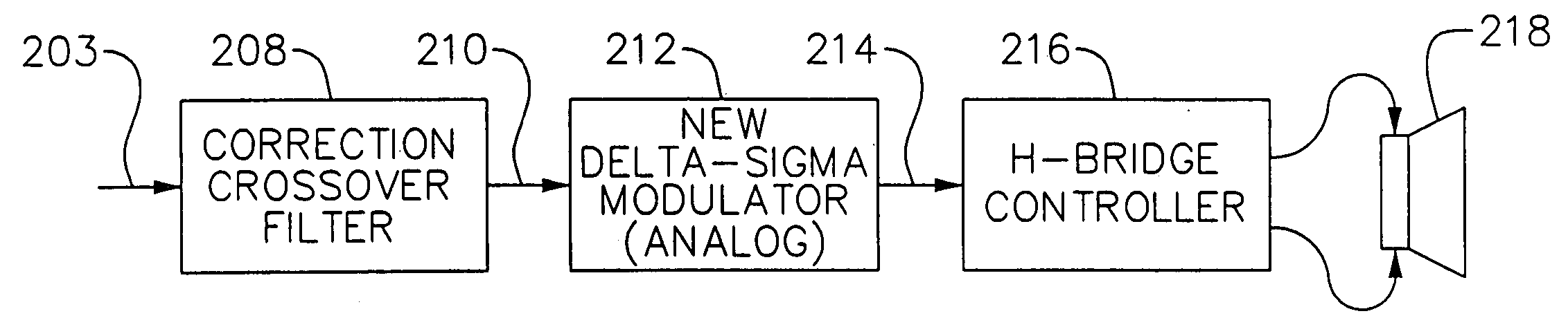
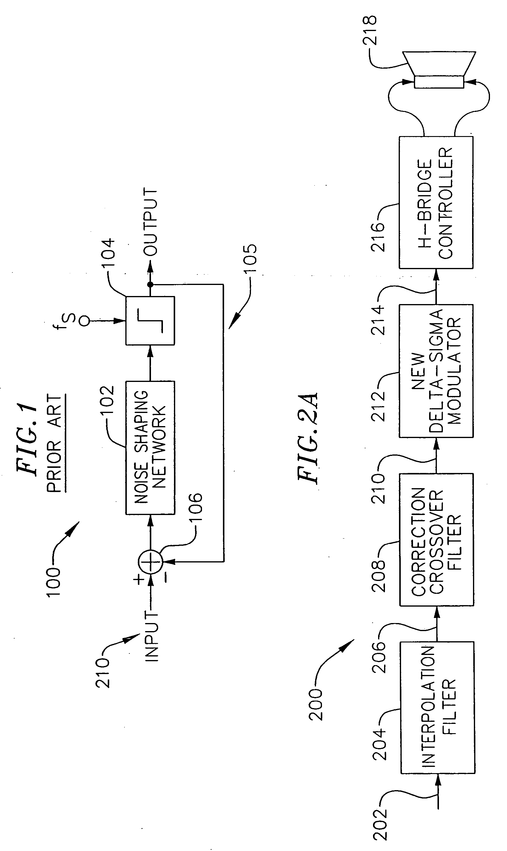
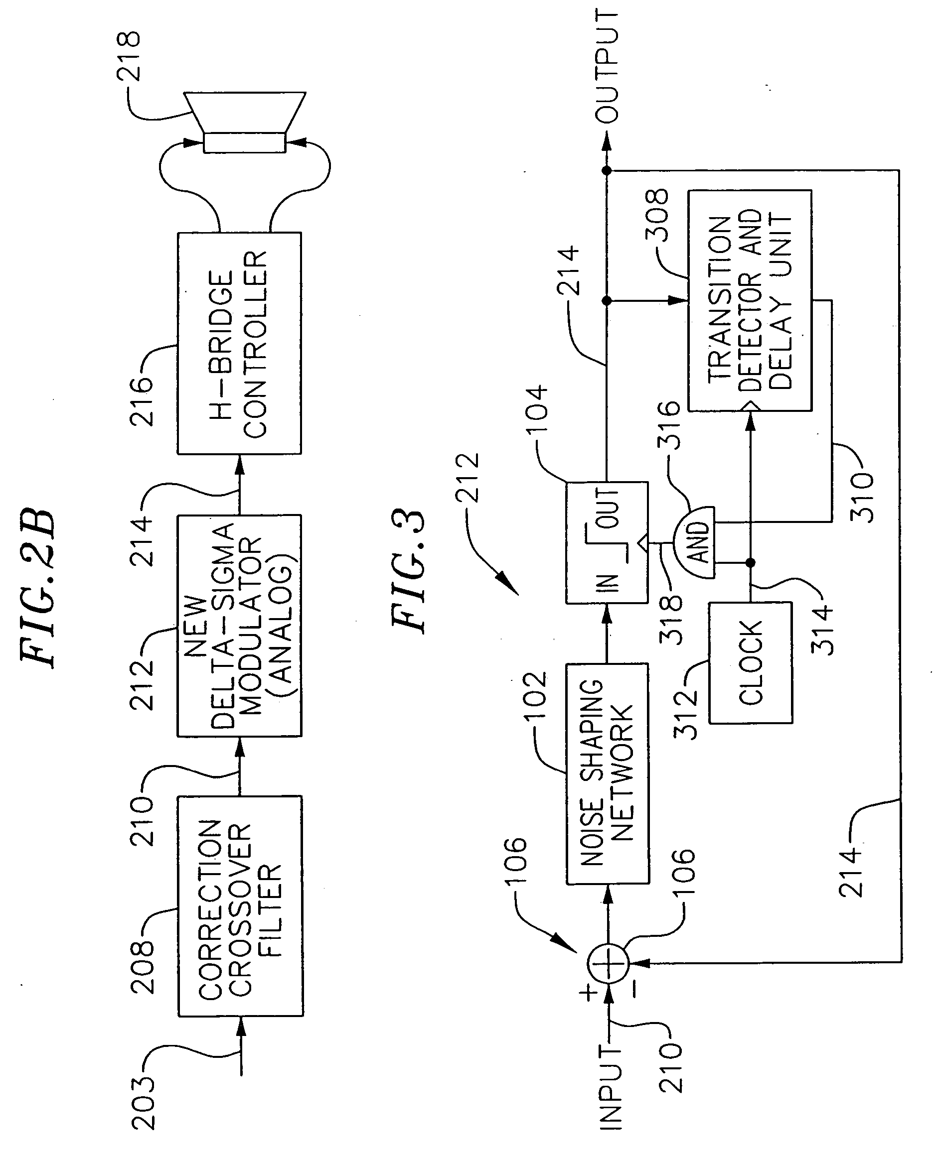
The present invention will be described in reference to a 1-bit digital amplifier 200. Referring to FIG. 2A, the input may be a digital signal 202 consisting of typically a 16 bit or 18 bit digital input. In this example, it may be a digital audio input at 48 kHz. A digital interpolation filter 204, converts the low rate, multi-bit signal 202 to a high rate multi-bit signal 206. The signal 206 consists of typically 16 to 22 bits in an audio application at a sample rate of typically 32 to 128 times the original sample rate at 202. An additional digital filter 208 can also be added, which performs two functions. First, it performs a typical crossover function com...


PUM


Abstract

A system and method of creating a highly efficient digital amplifier which can take either analog or digital inputs, and produce a high power accurate representation of the input to drive speakers or other low impedance load is described. The system employs a transition detector and delay unit which allows the comparator of the signal modulator to ignore its inputs for a pre-determined number of subsequent clock cycles once an output transition has been detected. Through the use of faster clocks and variable clock cycle skips upon the comparator's output transition, finer resolution of the feedback's clock period for noise-shaping purposes is achieved. Finer resolution of the clock period allows the present invention to employ a more aggressive noise-shaping than previously possible. In another aspect of the invention; additional delta-sigma modulator noise suppression is obtained by using the common bridge implementation of the power output stage with the improvement of configuring the bridge to create a 3-state condition instead of the conventional 2 states. By controlling the two halves of the bridge independently of one another, an output with 3 states makes for improved noise shaping performance.

Description

BACKGROUND OF THE INVENTION 1. Field of the Invention The present invention relates to the field of switching amplifiers. More specifically, the present invention relates to a novel method of sampling in the signal modulation stage of a digital amplifier to achieve a highly accurate representation of the input signal at substantial gain. 2. Description of the Related Art There have been various developments pertaining to oversampled, noise-shaping signal processing. These developments have been applicable to both continuous-time (analog) and discrete-time (digital or sampled analog) signals. The constant struggle in this field is to increase the efficiency of the amplifiers. Given the myriad of applications of sound applications in the electronics of today, it is apparent that an efficient audio amplification is highly desirable. In response to this need, attempts have been made to design switching audio amplifiers using oversampled, noise-shaping modulators, especially delta-s...

Claims


Application Information

Patent Timeline
IPC IPC(8): H03F3/217H03M3/02H03M7/32
CPCH03F3/2173H03F2200/331H03M3/496H03M7/3031H03M3/43H03M7/3006
Inventor OLSON, ERLENDOPRIS, ION
Owner AVAGO TECH WIRELESS IP SINGAPORE PTE
Why Eureka
Try Eureka