Vibrating mirror, optical scanner using vibrating mirror, and image reproducing and forming apparatus

a technology of vibrating mirrors and mirrors, applied in the direction of electrical equipment, instruments, electric/electrostrictive/magnetostrictive devices, etc., can solve the problems of limited durability of bearings, the type of vibrating mirrors is incapable of deflecting light beams over a wide range, and the ceiling to increase the rotational speed of the mirror, etc. achieve satisfactory imaging performance and maintain the flat surface of the mirror

Inactive Publication Date: 2005-02-10
RICOH KK
View PDF1 Cites 31 Cited by
  • Summary
  • Abstract
  • Description
  • Claims
  • Application Information

AI Technical Summary

Benefits of technology

It is an object of the present invention to overcome the above-described problems in the prior art, and to provide a vibrating mirror that can prevent dynamically arising waves and maintain the flatness of the mirror surface so as to achieve satisfactory imaging performance.

Problems solved by technology

However, there is a ceiling to increasing the rotational speed of the mirror because of various reasons, such as limitation in durability of the bearings, heat generation due to windage, and noise.
However, this type of vibrating mirror is incapable of deflecting a light beam over a wide range, unlike the conventional polygon mirror, because the size of the mirror surface and the sweep angle are small.
As a result, the mirror surface bends in a sinusoidal curve and the surface accuracy is degraded.
This is one of the factors that makes it difficult to increase the sweep angle to extend the imaging range even under an increased rotational force applied to the mirror.
The number of divided sections along the scanning line may be increased to compensate for the limited sweep angle; however, this results in undesirable increased cost.
This phenomenon causes the image to blur, reduces the resolution, and degrades the image quality.

Method used


Image

  • Vibrating mirror, optical scanner using vibrating mirror, and image reproducing and forming apparatus
  • Vibrating mirror, optical scanner using vibrating mirror, and image reproducing and forming apparatus
  • Vibrating mirror, optical scanner using vibrating mirror, and image reproducing and forming apparatus

Examples


Embodiment Construction

The preferred embodiments of the present invention are described below with reference to the attached drawings.

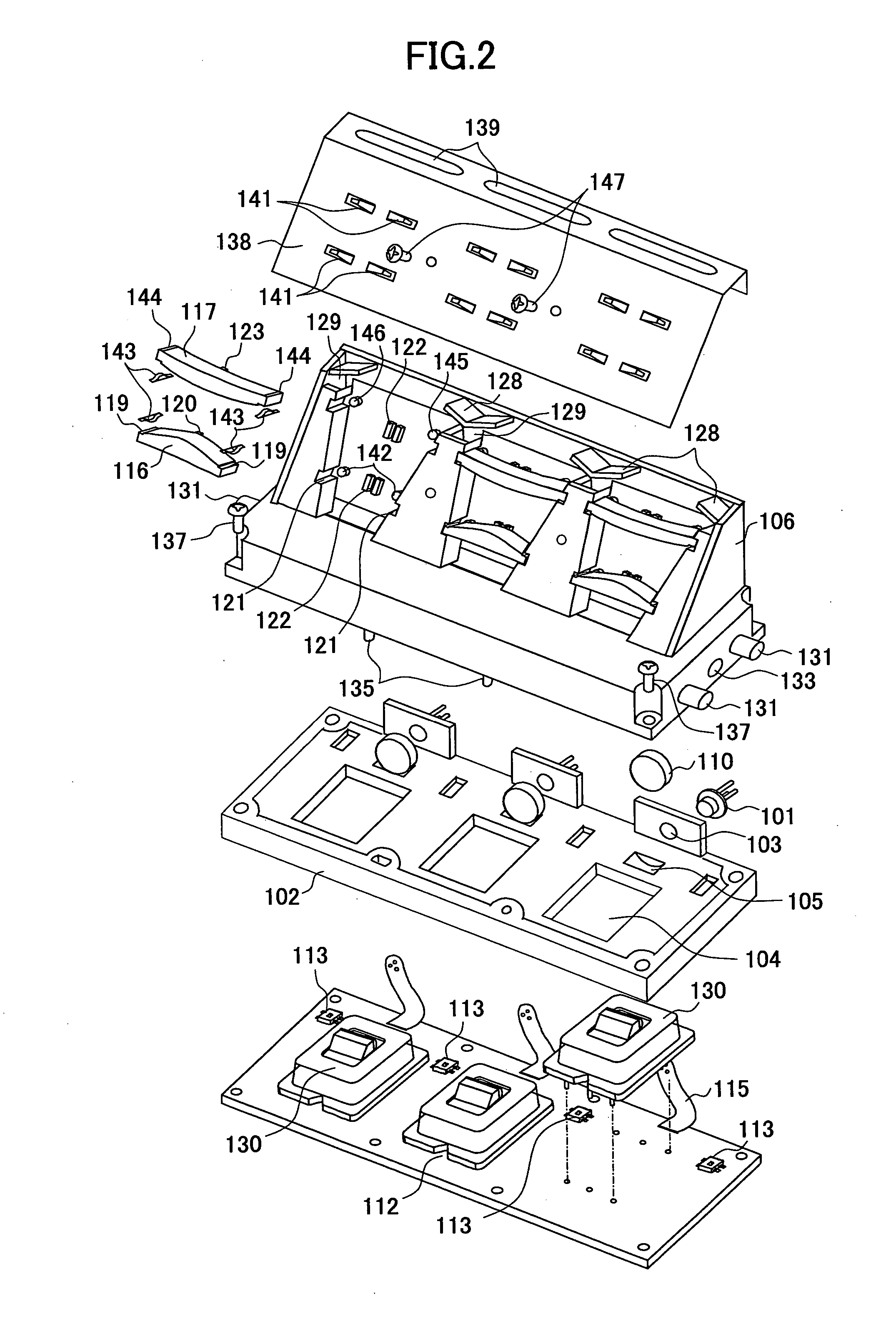
FIG. 2 is an exploded view of an optical scanning unit according to an embodiment of the invention, and FIG. 3 is a perspective view of the major part of the optical scanning unit of FIG. 2, showing the arrangement of the optical elements. FIG. 4A is an exploded view of the vibrating mirror module 130 shown in FIG. 3, and FIG. 4B illustrates the first substrate 206 and the second substrates 207 forming a vibrating mirror according to an embodiment of the invention. FIG. 5 is a cross-sectional view of the optical scanning unit shown in FIG. 2, taken along the slow scan cut plane.

In the preferred embodiment, three vibrating mirror modules 130 are used in an optical scanning unit, as illustrated in FIG. 2 and FIG. 3. Each of the vibrating mirror modules 130 (or optical scanning means) covers one third of the entire scanning line extending in the fast scan direction. Each v...


PUM


Abstract

A vibrating mirror comprises a moving mirror configured to deflect a light beam, a torsion bar coupled to the moving mirror and defining a rotational axis of the moving mirror, and a mirror driving part configured to produce a rotational force for causing the moving mirror to oscillate, wherein the torsion bar is coupled to the moving mirror at connecting positions offset from the rotational axis by a distance r/2 in opposite directions so as to satisfy r>A/6, where A is the width of the moving mirror perpendicular to the rotational axis.

Description

BACKGROUND OF THE INVENTION 1. Field of the Invention The present invention relates to a vibrating mirror (or a deflecting mirror) used in, for example, optical scanners, optical-scan display devices, or in-vehicle laser radars. The present invention also relates to an optical scanner with a vibrating mirror, and to an image reproducing / forming apparatus, such as digital copying machines, laser printers, laser plotters, laser facsimile machines, etc., employing the optical scanner. 2. Description of Related Art In conventional optical scanners, polygon mirrors or galvanometer mirrors are used to deflect beams for writing images. In order to achieve high-resolution high-speed printing operations, the rotational speed of these mirrors has to be increased. However, there is a ceiling to increasing the rotational speed of the mirror because of various reasons, such as limitation in durability of the bearings, heat generation due to windage, and noise. On the other hand, optical def...

Claims


Application Information

Patent Timeline
Patent Type & Authority Applications(United States)
IPC IPC(8): B81B3/00G02B26/08G02B26/10H04N1/036H04N1/113H04N1/12
CPCG02B26/0841G02B26/105H04N2201/0082H04N1/12H04N1/1135
Inventor NAKAJIMA, TOMOHIRO
Owner RICOH KK
Why Eureka
Try Eureka