Projection objective for microlithography

a technology of projection objective and microlithography, which is applied in the direction of lenses, photomechanical equipment, instruments, etc., can solve the problems of increasing costs, and achieve the effects of strong lens dispersion, easy access to processing equipment, and easy production and testing of lens surfaces

Inactive Publication Date: 2005-02-10
CARL ZEISS SMT GMBH
View PDF5 Cites 0 Cited by
  • Summary
  • Abstract
  • Description
  • Claims
  • Application Information

AI Technical Summary

Benefits of technology

It is an advantage of the invention to provide a refractive microlithographic projection objective, wherein all aspheric lens surfaces have a vertex radius (R) of at least 300-mm. Thus the aspheric surfaces are provided on long radii, since the production and testing is easier for lens surfaces with long radii. These surfaces are easily accessible to processing equipment because of their low curvature. In particular, surfaces with long radii are accessible with Cartesian coordinates for tactile measurement processes.
It has been found to be advantageous to use at least two different materials for achromatization, for projection objectives designed for an illumination wavelength of less than 200 nm, because of the stronger dispersion of the lenses, even with the use of narrowband light sources. In particular, fluorides, especially CaF2, are known as suitable materials, besides quartz glass.
It has been found to be advantageous to provide at least two lenses of CaF2, which are arranged before an aperture stop in the fifth lens group, for the correction of color transverse errors.
It has been found to be advantageous for the further correction of color errors to integrate an achromat after the aperture stop by means of a positive CaF2 lens and a following negative quartz lens. This arrangement has a favorable effect on the correction of the spherical portions. In particular, longitudinal color errors can be corrected by the lenses after the aperture stop.
A reduction of the longitudinal error already results in general from the shortening of the length of the projection objective. Thus a good achromatization with a reduced use of CaF2 lenses can be attained with the objective according to the invention.

Problems solved by technology

This has a positive effect on the production costs, since it is the production of highly accurate aspheric surfaces that requires considerable technological effort, which entails increased costs.

Method used


Image

  • Projection objective for microlithography
  • Projection objective for microlithography
  • Projection objective for microlithography

Examples


Embodiment Construction

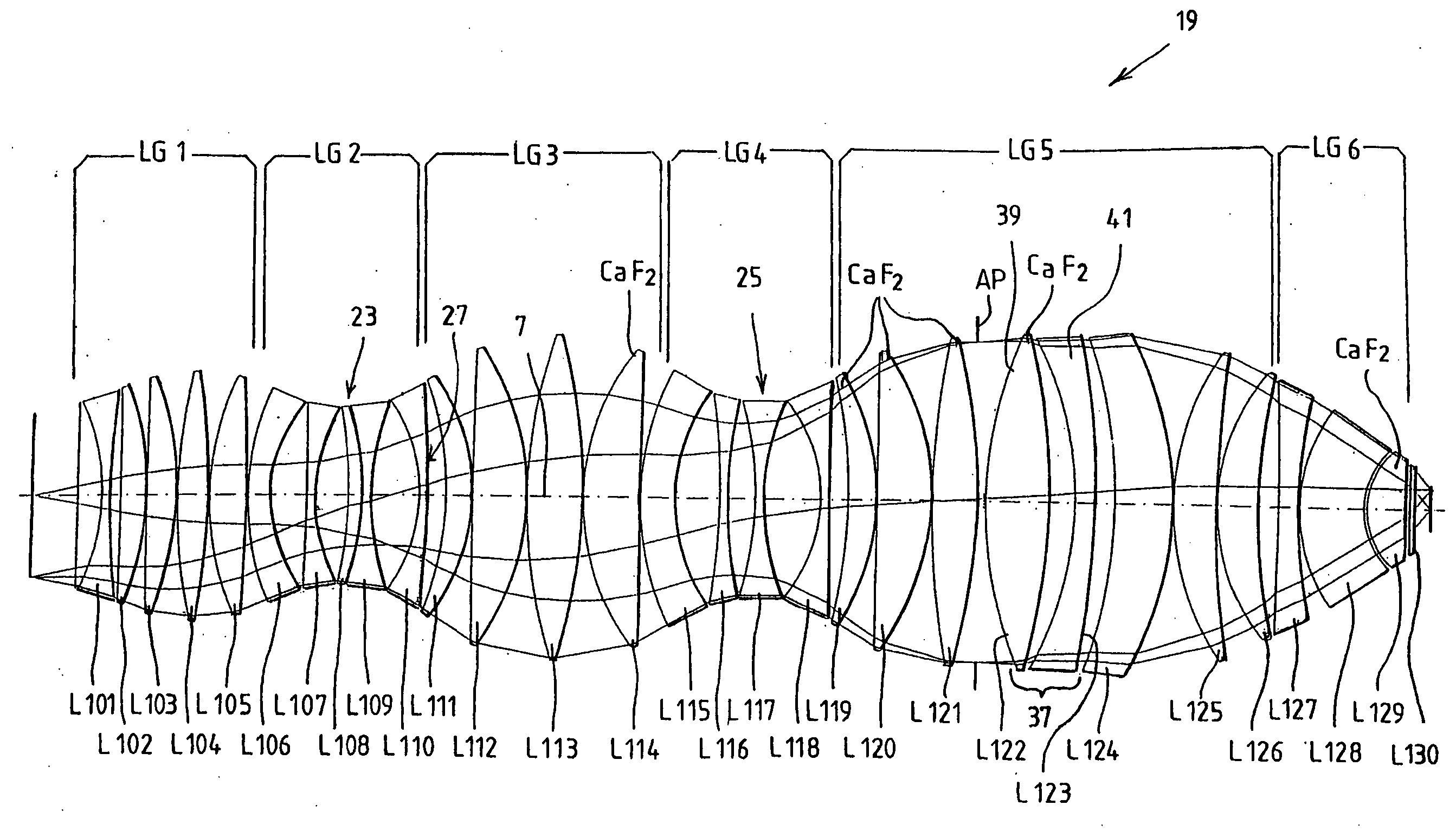
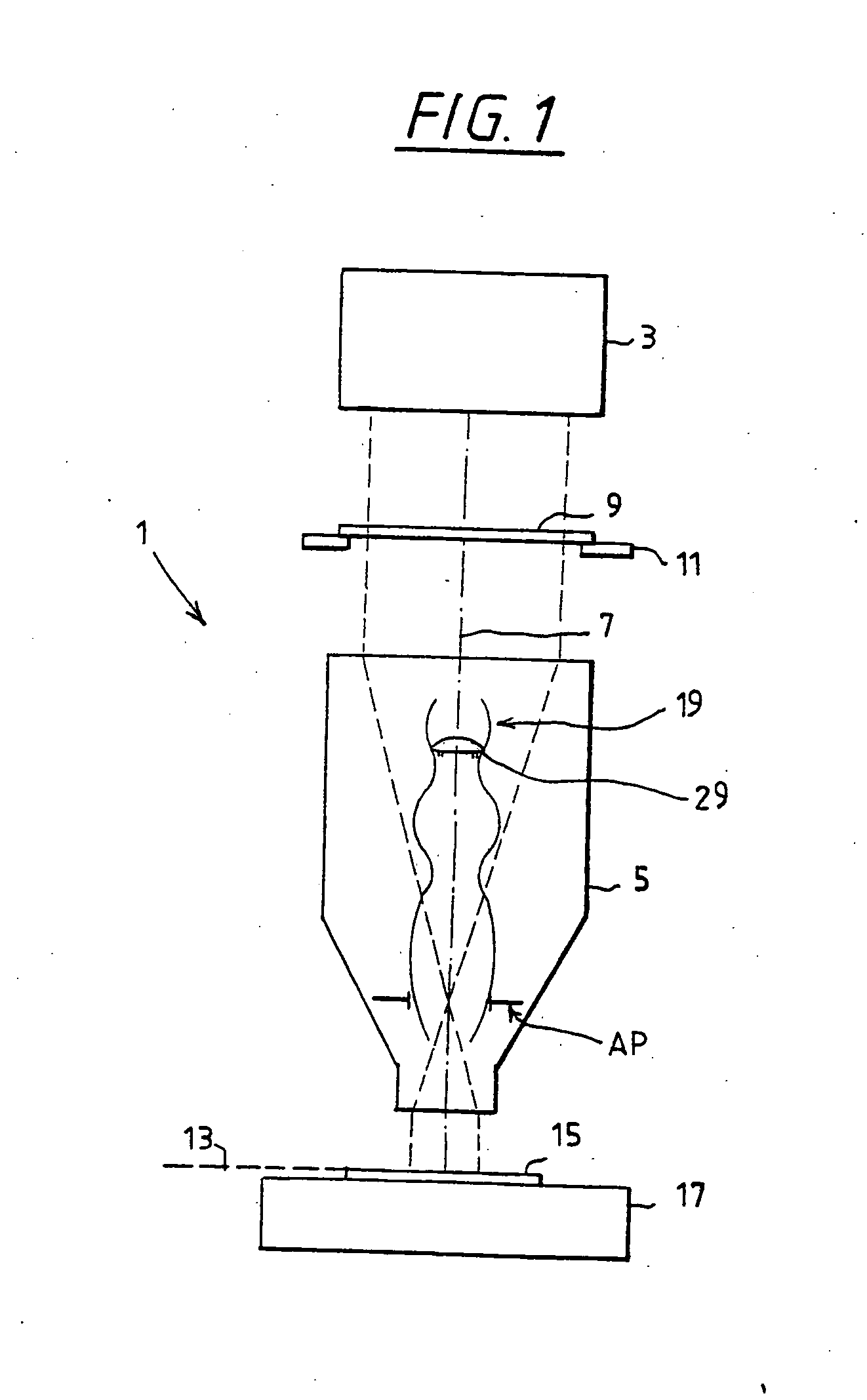
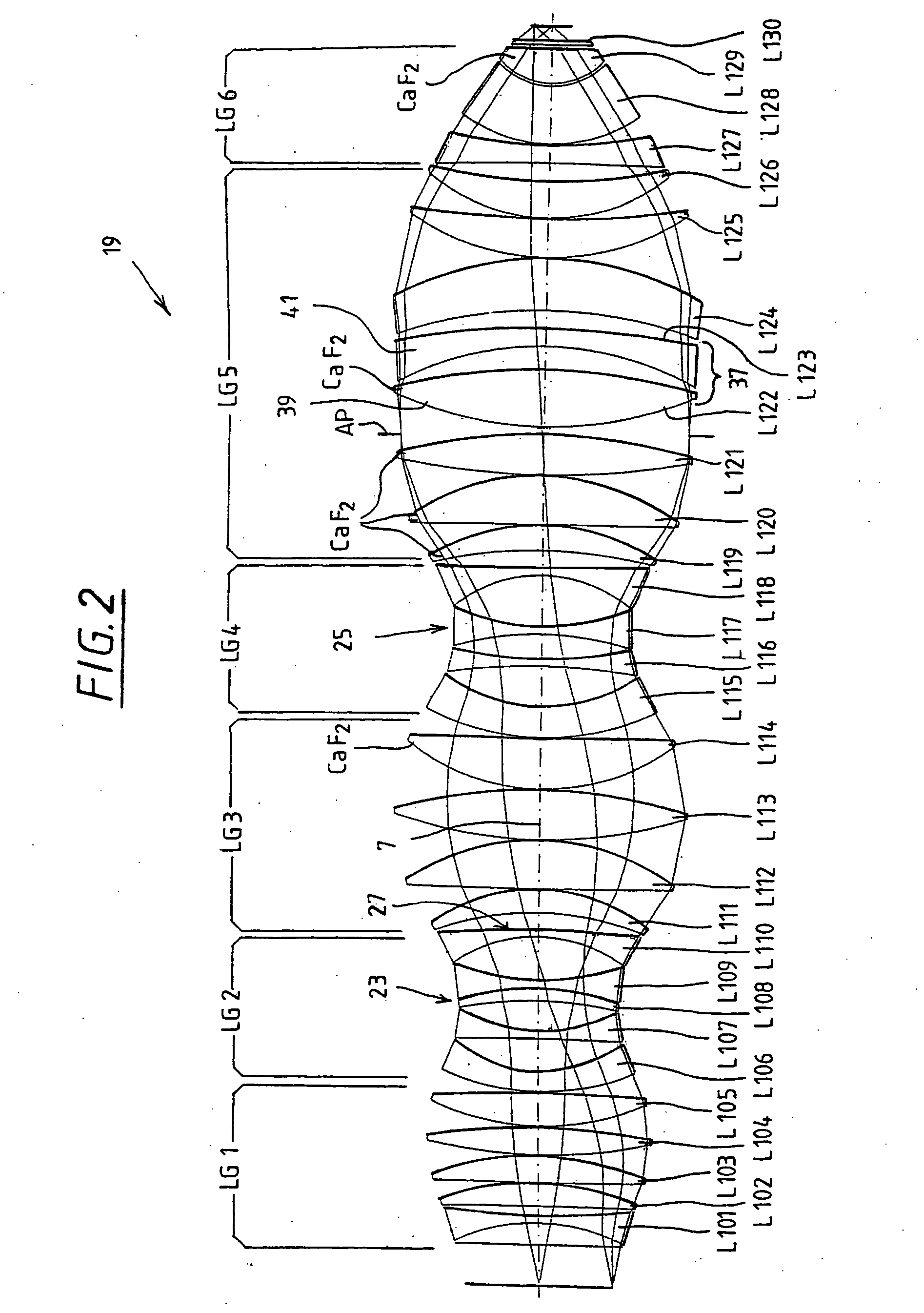
The principle of the construction of a projection exposure device is first described with the aid of FIG. 1. The projection exposure device 1 has an illuminating device 3 and a projection objective 5. The projection objective includes a lens arrangement 19 with an aperture stop AP, an optical axis 7 being defined by the lens arrangement 19. A mask 9 is arranged between the illuminating device 3 and the projection objective 5, and is supported in the beam path by means of a mask holder 11. Such masks 9 used in microlithography have a micrometer to nanometer structure, which is reduced by means of the projection objective 5 by a factor of up to 10, particularly a factor of four, and is imaged on an image plane 13. A substrate positioned by a substrate holder 17 or a wafer 15 is supported in the image plane 13. The minimum structures which are still resolvable depend on the wavelength λ of the light used for illumination, and also on the numerical aperture of the projection objective ...


PUM

PropertyMeasurementUnit
diameteraaaaaaaaaa
diameteraaaaaaaaaa
vertex radiusaaaaaaaaaa

Abstract

The invention relates to a projection lens comprising a lens assembly that has at least one first narrowing of the group of light beams. A lens with a non-spherical surface is located in front of and/or behind the first narrowing.

Description

STATEMENT REGARDING FEDERAL SPONSORED RESEARCH OR DEVELOPMENT Not Applicable. REFERENCE TO A MICROFICHE APPENDIX Not Applicable. BACKGROUND OF THE INVENTION 1. Technical Field The invention relates to a projection objective with a lens arrangement, which can be divided into six lens groups. The first, third, fifth and sixth lens groups have positive power and the second and fourth lens groups respectively have negative power. The division of the lens system into lens groups is described in more detail hereinafter, based on the direction of propagation of the radiation. The first lens group is positive and ends with a lens of positive power. A bulge is formed by the first lens group; it is unimportant if negative lenses are also arranged in the bulge. The second lens group is of negative total power. This second lens group has as its first lens a lens having a concave lens surface toward the image. This second lens group substantially describes a waist. Here, also it is not of ...

Claims


Application Information

Patent Timeline
Patent Type & Authority Applications(United States)
IPC IPC(8): G02B13/24G02B13/14G02B13/18G03F7/20H01L21/027
CPCG03F7/70241G02B13/143G02B13/18
Inventor SCHUSTER, KARL-HEINZ
Owner CARL ZEISS SMT GMBH
Why Eureka
Try Eureka