Power supply and control method for injector driver module

a technology of injector driver and power supply, which is applied in the direction of electric control, machines/engines, relays, etc., can solve the problems of large power loss in the injector driver module, radio reception interference, and unsuitable 12v vehicle batteries for operating the injector coil directly, so as to reduce emi emissions, reduce power loss, and prolong the switching time during modulation

Inactive Publication Date: 2005-02-10
SIEMENS VDO AUTOMOTIVE CORP
View PDF7 Cites 13 Cited by
  • Summary
  • Abstract
  • Description
  • Claims
  • Application Information

AI Technical Summary

Benefits of technology

[0008] In one embodiment, both the first and the second converters are connected to the load so that a supply voltage to the load is the sum of the first and second output voltages during a magnetization phase. The high supply voltage quickly generates a peak current in the load. Once the peak current level has been reached, one of the converters is removed from the load to lower the supply voltage during a travel phase. During this stage, the voltage can be controlled to keep the current at a desired level. The current can then be lowered and later dropped to zero during hold and recuperation phases. Current control can be conducted through, for example, pulse width modulation. Lowering the supply voltage allows the pulse width modulation to be conducted at lower voltage levels, thereby lengthening the switching time during modulation, reducing power losses, and reducing EMI emissions.

Problems solved by technology

This high voltage requirement makes a conventional 12V vehicle battery unsuitable for operating the injector coil directly.
However, rapid on / off switching of such a high supply voltage introduces electromagnetic radiation (i.e., EMI emissions), which causes radio reception interference, particularly in the AM band.
Moreover, the high power requirements cause large power losses in the injector driver module.

Method used


Image

  • Power supply and control method for injector driver module
  • Power supply and control method for injector driver module
  • Power supply and control method for injector driver module

Examples


Embodiment Construction

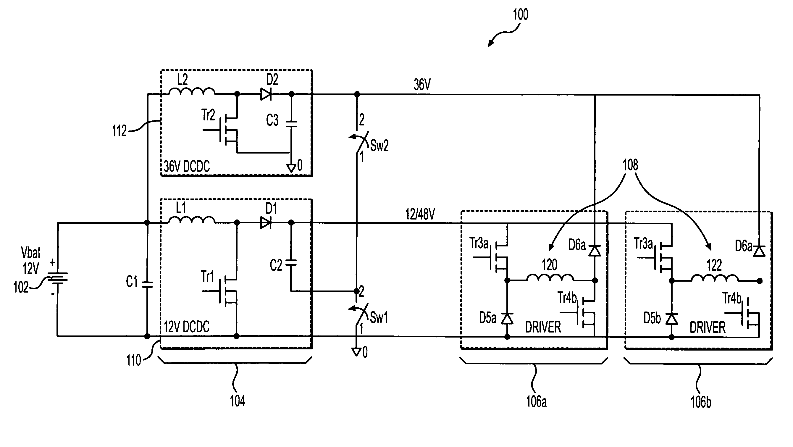
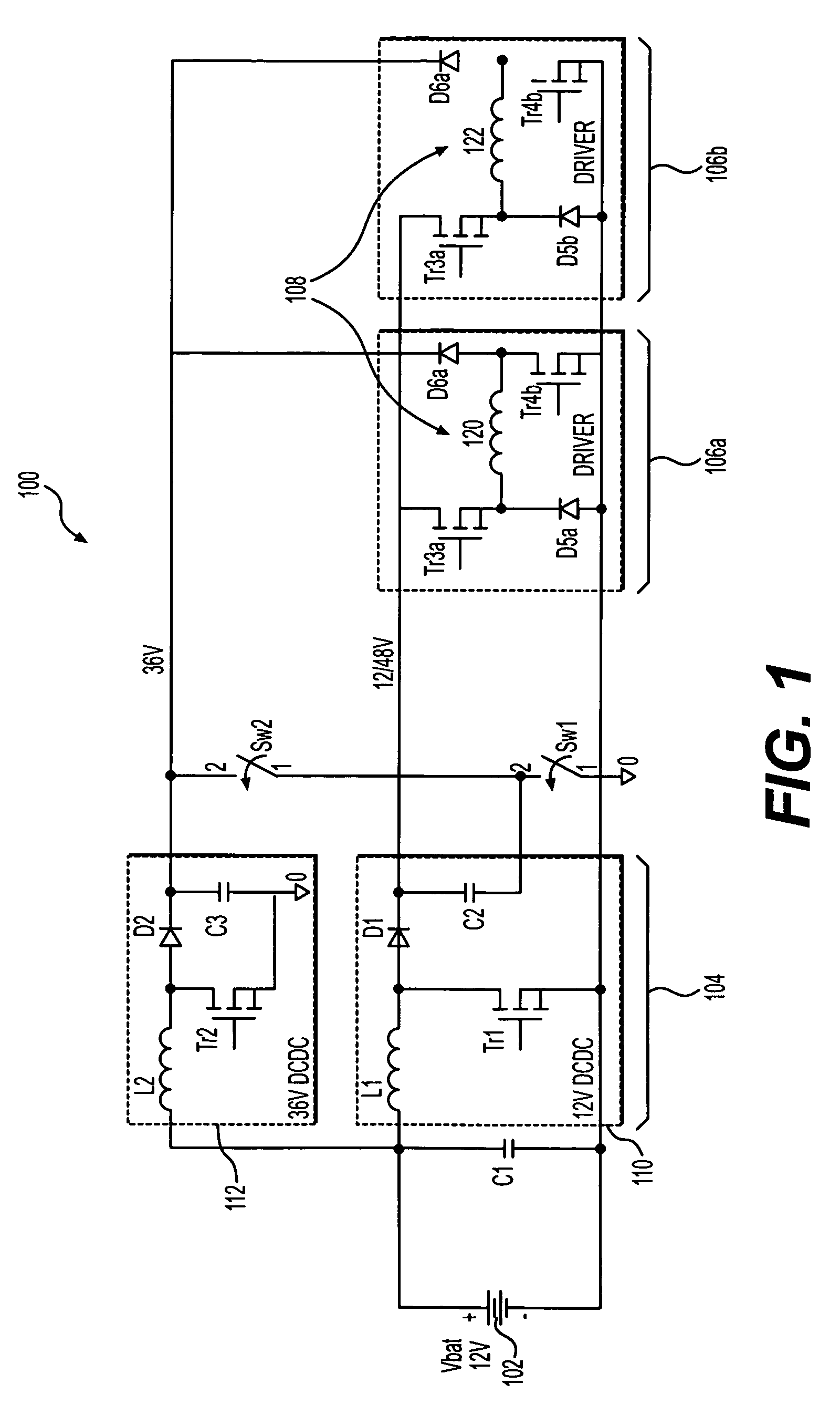
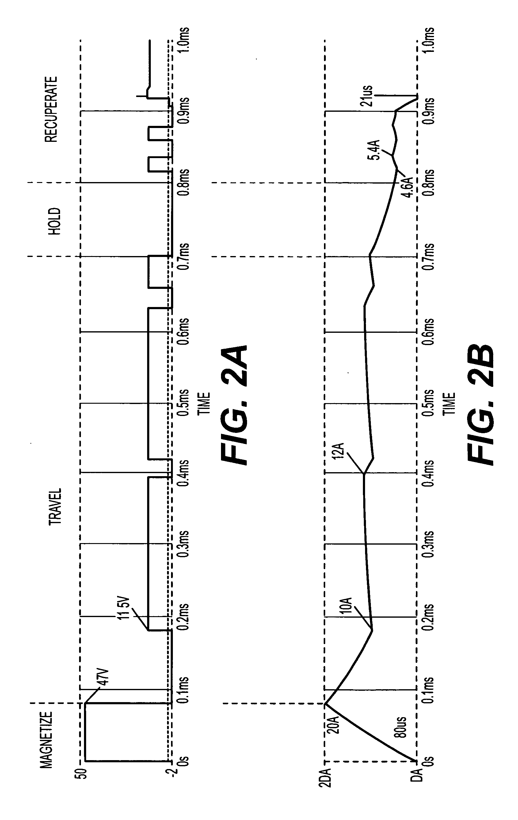
[0014] The invention is directed to an injector driver module having a power supply and a load comprising one or more injector coils. Generally, a voltage across the injector coil is increased until current through the coil reaches a selected peak coil current level. Although the invention still conducts fast voltage transitions, it does so to a lesser extent and with increased switching times. The invention includes a novel power supply that can control the coil current in this manner. As a result, the invention generates fewer EMI emissions and reduces power losses in the module.

[0015]FIG. 1 illustrates an injector driver module 100 according to one embodiment of the invention. The module 100 is powered by any appropriate power source, such as a vehicle battery 102 (e.g., a 12V battery), and includes a power supply stage 104 and at least one driver stage having at least one injector coil load 108 that operates a fuel injector (not shown). The illustrated embodiment shows a module...


PUM


Abstract

An injector driver module includes a first converter and a second converter connected between a power supply and the load. The first converter generates a first voltage output and the second converter generates a second voltage output from the power supply. Switches control the level of the supply voltage so that the voltage applied to the load can be varied depending on an operational phase of the driver. Control over the current through the load can be therefore be conducted via pulse width modulation at lower voltage levels, thereby lengthening the switching time during modulation, reducing power losses, and reducing EMI emissions.

Description

REFERENCE TO RELATED APPLICATIONS [0001] The application claims priority to U.S. Provisional Application No. 60 / 489,008, which was filed on Jul. 21, 2003.TECHNICAL FIELD [0002] The present invention relates to a driver module for a fluid injector. BACKGROUND OF THE INVENTION [0003] Vehicles use injector driver modules to operate magnetic fuel injectors. Currently known injector drive modules use an injector coil that is activated with short current pulses at a selected current level (e.g., 20A). Because the injector coil is a natural inductor, it requires a high initial voltage to bring the current level in the injector coil to the selected level in a short time period. This high voltage requirement makes a conventional 12V vehicle battery unsuitable for operating the injector coil directly. [0004] To boost the vehicle battery voltage, a DC-DC converter is incorporated to increase the supply voltage for the injector coil to a desired high voltage level (e.g., 48V). This higher suppl...

Claims


Application Information

Patent Timeline
Patent Type & Authority Applications(United States)
IPC IPC(8): F02D41/20
CPCF02D2041/2027F02D2041/2051F02D2041/2003F02D41/20F02D2041/1432F02D2041/2079
Inventor BOLZ, STEPHANMAKAR, SIMONHILTUNEN, LARRY
Owner SIEMENS VDO AUTOMOTIVE CORP
Why Eureka
Try Eureka