
Excimer or molecular fluorine laser system with precision timing

a technology of excimer or molecular fluorine and laser system, which is applied in the direction of laser details, active medium materials, electrical equipment, etc., can solve the problems of further complexity and expense, and the desire for such submicron features comes with a pri

Active Publication Date: 2005-02-10
COHERENT GMBH
View PDF4 Cites 33 Cited by
  • Summary
  • Abstract
  • Description
  • Claims
  • Application Information

AI Technical Summary

Problems solved by technology

The desire for such submicron features comes with a price, however, as there is a need for improved processing equipment capable of consistently and reliably generating such features.
Further, as excimer laser systems are the next generation to be used for micro-lithography applications, the demand of semiconductor manufacturers for powers of 40 W or more to support throughput requirements leads to further complexity and expense.

Method used


Image

  • Excimer or molecular fluorine laser system with precision timing
  • Excimer or molecular fluorine laser system with precision timing
  • Excimer or molecular fluorine laser system with precision timing

Examples


Embodiment Construction

As semiconductor manufacturers move toward the production of chips with smaller sizes, the requirements on the processing and manufacturing equipment, including the laser light sources, are ever increasing. In laser systems used for photolithography applications, for example, it would be desirable to move toward higher repetition rates, increased energy stability and dose control, increased system uptime, narrower output emission bandwidths, improved wavelength and bandwidth accuracy, and improved compatibility with stepper / scanner imaging systems. It also would be desirable to provide lithography light sources that deliver high spectral purity and extreme power, but that also deliver a low cost chip production. Requirements of semiconductor manufacturers for higher power and tighter bandwidth can place excessive and often competing demands on current single-chamber-based light sources. Many of these obstacles can be overcome by taking advantage of a dual-gas-discharge-chamber tech...


PUM


Abstract

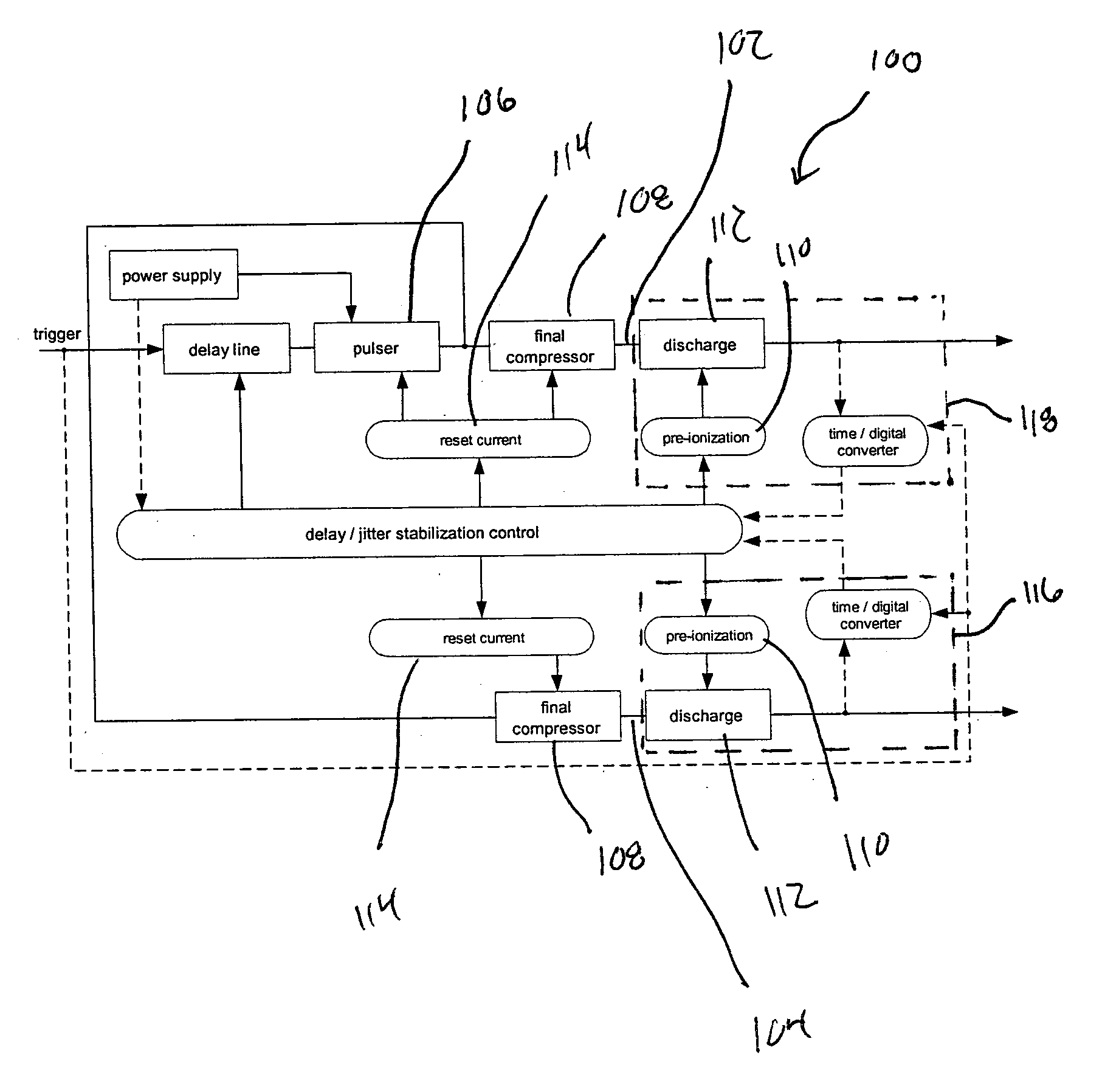
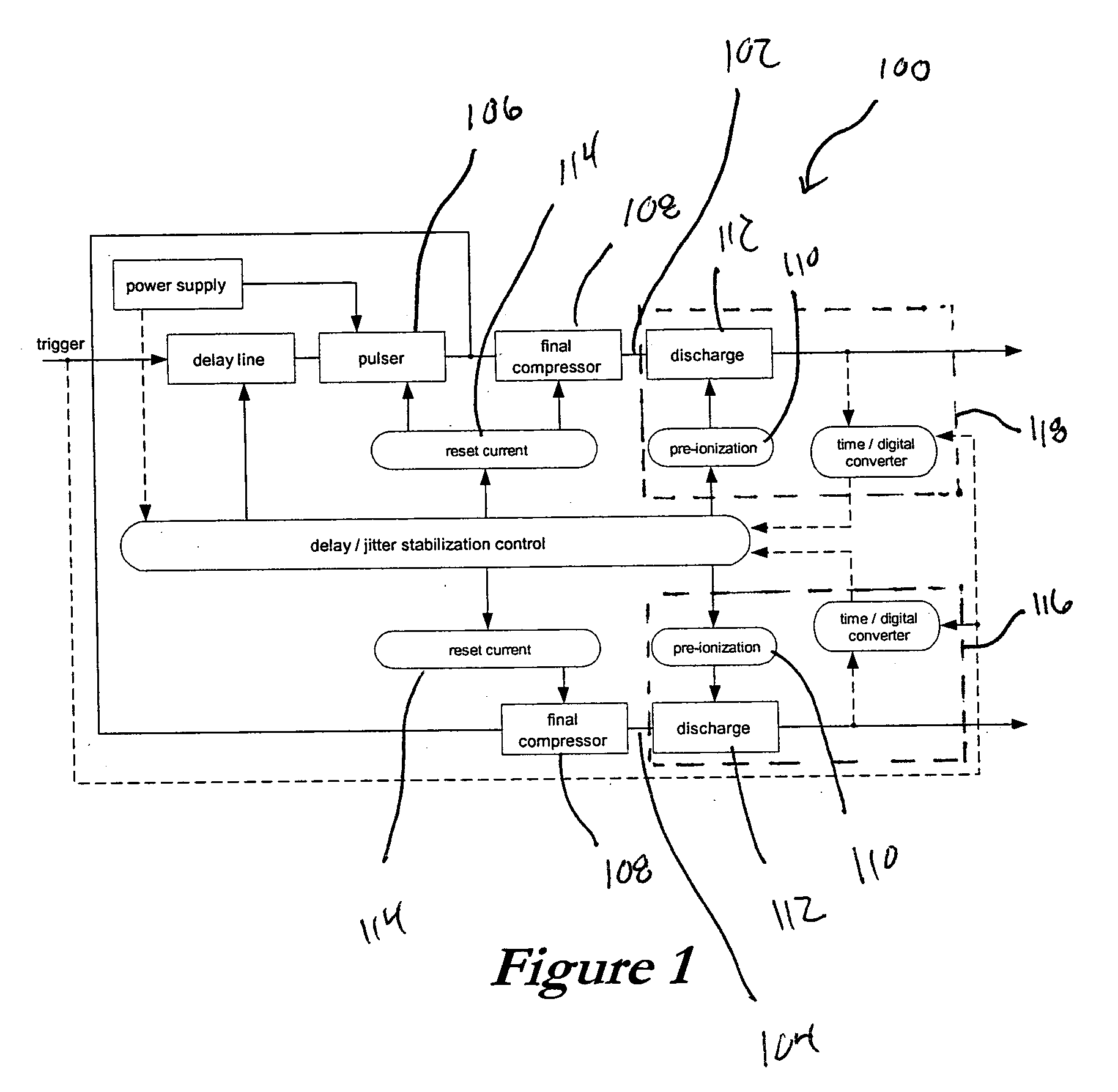
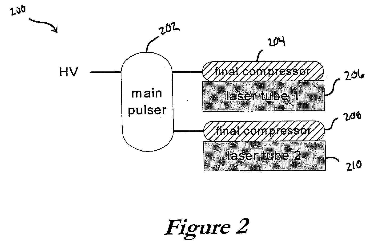
A Master Oscillator (MO)—Power Amplifier (PA) configuration (MOPA) can be used advantageously in an excimer laser system for micro-lithography applications, where semiconductor manufacturers demand powers of 40 W or more in order to support the throughput requirements of advanced lithography scanner systems. The timing of discharges in discharge chambers of the MO and PA can be precisely controlled using a common pulser to drive the respective chambers. The timing of the discharges further can be controlled through the timing of the pre-ionization in the chambers, or through control of the reset current in the final compression stages of the pulser. A common pulser, or separate pulser circuits, also can be actively controlled in time using a feedback loop, with precision timing being achieved through control of the pre-ionization in each individual discharge chamber. Yet another system provides for real-time compensation of time delay jitter of discharge pulses in the chambers.

Description

CROSS-REFERENCE TO RELATED APPLICATIONS The following applications are cross-referenced and hereby incorporated herein by reference: U.S. Patent application No. [Not Yet Assigned], entitled “MASTER OSCILLATOR—POWER AMPLIFIER EXCIMER LASER SYSTEM,” to Gongxue Hua et al., filed Oct. 30, 2003, Atty. Docket No. LMPY-18330; U.S. Pat. No. 6,226,307, entitled “MAGNETIC SWITCH CONTROLLED POWER SUPPLY ISOLATOR AND THYRISTOR COMMUTATING CIRCUIT,” to Rainer Desor et al., Nov. 2, 1999; and U.S. Pat. No. 6,005,880, entitled “PRECISION VARIABLE DELAY USING SATURABLE INDUCTORS,” to Dirk Basting et al., filed Mar. 21, 1997. TECHNICAL FIELD OF THE INVENTION The present invention relates to synchronization and time delays in high power excimer or molecular fluorine lasers, such as are useful for applications in microlithography and semiconductor processing. BACKGROUND Semiconductor manufacturers are currently using deep ultraviolet (DUV) lithography tools based on KrF-excimer laser systems, ope...

Claims


Application Information

Patent Timeline
Patent Type & Authority Applications(United States)
IPC IPC(8): H01S3/00H01S3/0971H01S3/22H01S3/225H01S3/23
CPCH01S3/073H01S3/09702H01S3/2258H01S3/225H01S3/09713
Inventor BASTING, DIRKGOVORKOV, SERGEIPAETZEL, RAINERBRAGIN, IGORTARGSDORF, ANDREAS
Owner COHERENT GMBH
Learn More