Method and apparatus of estimating non-linear amplifier response in an overlaid communication system

a communication system and amplifier technology, applied in the field of communication systems, can solve the problems of system capacity constraint, system capacity increase, and system service disruption, and achieve the effects of accurate estimation of amplifier response, accurate reconstruction of received signals, and removal of bias

Inactive Publication Date: 2005-02-10
HUGHES NETWORK SYST
View PDF4 Cites 53 Cited by
  • Summary
  • Abstract
  • Description
  • Claims
  • Application Information

AI Technical Summary

Benefits of technology

These and other needs are addressed by the present invention, wherein an approach is provided for estimating a Travelling Wave Tube Amplifier (TWTA) real-time response for multiuser satellite communication systems that experience uplink noise, downlink noise, and severe interference from the ground stations (e.g., remote terminals). The approach uses an iterative curve-fitting algorithm based on the time-domain coarse estimates of TWTA response to remove the bias caused by the uplink interference. The estimates of the TWTA response can be feed to a non-linearity (or interference) compensation or cancellation module to accurately reconstruct the received signals. This approach advantageously provides accurate estimation of the amplifier response, even with large uplink interference. Additionally, the approach advantageously does not require additional training signals, thereby promoting efficient use of precious bandwidth.

Problems solved by technology

Satellite communication systems are susceptible to service disruptions stemming from changing channel conditions, such as fading because of weather disturbances.
Additionally, such systems cannot readily increase capacity as the number of satellite transponders is fixed.
Channel interference also constrains the system capacity.
Further, these satellite transponders introduce non-linear behavior of the communication channels by utilizing non-linear high power amplifiers.
As a result, spectral efficiency is reduced.
The drawback, however, is that a large number of frequencies are required when terminals are added to the system 2000.
Conventional approaches assume that both inbounds and outbound share an ideal linear channel; however, because Travelling Wave Tube Amplifiers (TWTAs) are used, this assumption is problematic.
As a result of this assumption, large uncompensated mutual interference exists between the inbound signals and the outbound signals.
However, transmitted power levels must be very low in order to minimize interference to the forward link; and as a result, spread spectrum techniques results in very limited capacity of each link, such that information bit rates on the return links tend to be low.
A drawback with this approach is that overall system capacity is reduced.
TWTA exhibits severe non-linearity when operating close to its saturation point, with its response drifting continually due to environment change.
Conventional systems fail to compensate for this non-linear behavior.
Further, the transponder introduces group delay stemming from a noise-limiting filter applied before the amplifier.
One drawback is that to track the real-time response, the TWTAs need to be constantly swept with the CW signals, which consume extra transmission bandwidth.
Another drawback concerns the lack of robustness of the uplink interference and noise.
Unfortunately, due to the limitation of existing test equipment, this two tone scheme is conducted in the frequency domain based on some coarse approximations, and thus, lacks sufficient accuracy.
The non-linear effects and the group delay impede performance of a shared transponder scheme.
However, conventional techniques are not applicable to spectrum sharing.

Method used


Image

  • Method and apparatus of estimating non-linear amplifier response in an overlaid communication system
  • Method and apparatus of estimating non-linear amplifier response in an overlaid communication system
  • Method and apparatus of estimating non-linear amplifier response in an overlaid communication system

Examples


Embodiment Construction

A method, apparatus, and software for estimating non-linear characteristics of an amplifier used to amplify a composite signal in a radio communication system, are described. In the following description, for the purposes of explanation, numerous specific details are set forth in order to provide a thorough understanding of the present invention. It is apparent, however, to one skilled in the art that the present invention may be practiced without these specific details or with an equivalent arrangement. In other instances, well-known structures and devices are shown in block diagram form in order to avoid unnecessarily obscuring the present invention.

Although embodiments of the present invention are explained with respect to a satellite communication system, it is recognized that the present invention can be practiced in any type of radio communication system, including a microwave systems, cellular systems, packet radio networks, etc.

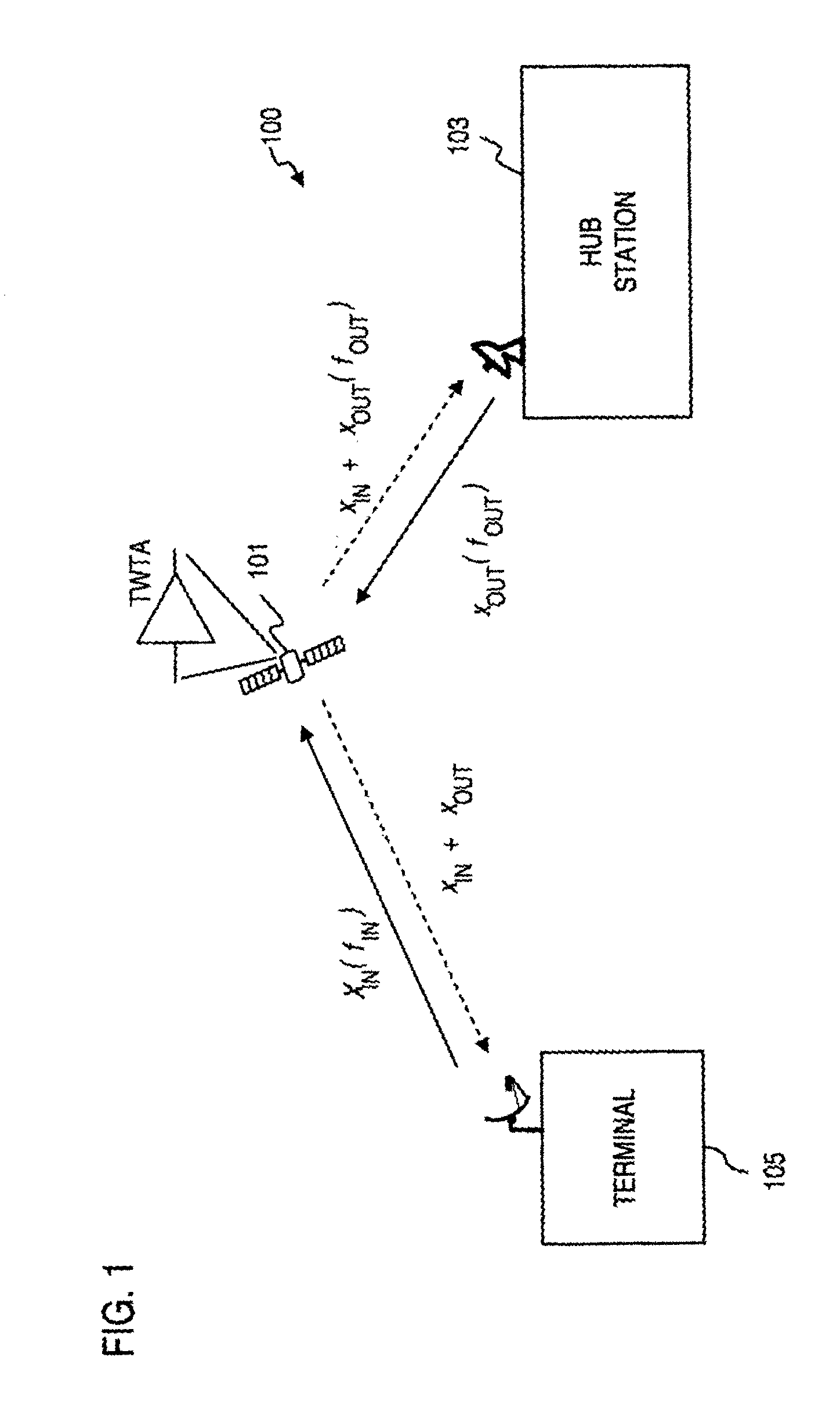
FIG. 1 is a diagram of a radio communication ...


PUM


Abstract

An approach is provided estimating non-linear characteristics of an amplifier (such as a Travelling Wave Tube Amplifier) used to amplify a composite signal in a radio communication system. The composite signal, which includes a plurality of inbound signals overlay on an outbound signal, is sampled. The outbound signal is utilized as a training signal. Coarse estimates of the response of the amplifier is generated based on the samples of the composite signal and the training signal. Further, the interference associated with the inbound signals are removed from the estimation of the response of the amplifier by curve-fitting and estimating interference characteristics of the composite signal. An estimated response of the amplifier is thus output, and can be utilized to provide accurate non-linearity compensation and cancellation.

Description

FIELD OF THE INVENTION The present invention relates to a communications system, and more particularly to estimating amplifier response in a radio communication system. BACKGROUND OF THE INVENTION Modern radio communication systems, such as satellite networks, provide a pervasive and reliable infrastructure to distribute voice, data, and video signals for global exchange and broadcast of information. These radio communication systems have emerged as a viable option to terrestrial communication systems. Satellite communication systems are susceptible to service disruptions stemming from changing channel conditions, such as fading because of weather disturbances. Additionally, such systems cannot readily increase capacity as the number of satellite transponders is fixed. Channel interference also constrains the system capacity. Further, these satellite transponders introduce non-linear behavior of the communication channels by utilizing non-linear high power amplifiers. This non-lin...

Claims


Application Information

Patent Timeline
Patent Type & Authority Applications(United States)
IPC IPC(8): H04B1/04H04B7/185
CPCH04B7/18515H04B1/0475
Inventor JIANG, YIMINSUN, FENG-WEN
Owner HUGHES NETWORK SYST
Why Eureka
Try Eureka