Architectures, circuits, systems and methods for reducing latency in data communications

a technology of data communication and architecture, applied in the field of data communication, can solve the problems of data transmission across conventional serial transmission media, false data, and certain minimum lengths that are reasonably likely to have some jitter, and achieve the effect of reducing the number of clock cycles required

Active Publication Date: 2005-02-10
MARVELL ASIA PTE LTD
View PDF9 Cites 49 Cited by
  • Summary
  • Abstract
  • Description
  • Claims
  • Application Information

AI Technical Summary

Benefits of technology

[0009] The present invention advantageously reduces the number of clock cycles required for data to be transmitted and/or repeated from one device to

Problems solved by technology

Data transmitted across conventional serial transmission media (e.g., copper wire, optical fiber) having a certain minimum length is reasonably likely to have some jitter.
In some cases, the jitter in the incoming data stream may cause glitches, false data, incorrect processing operations (such as incorrect clock recovery adjustments), and other data transmission

Method used


Image

  • Architectures, circuits, systems and methods for reducing latency in data communications
  • Architectures, circuits, systems and methods for reducing latency in data communications
  • Architectures, circuits, systems and methods for reducing latency in data communications

Examples


Embodiment Construction

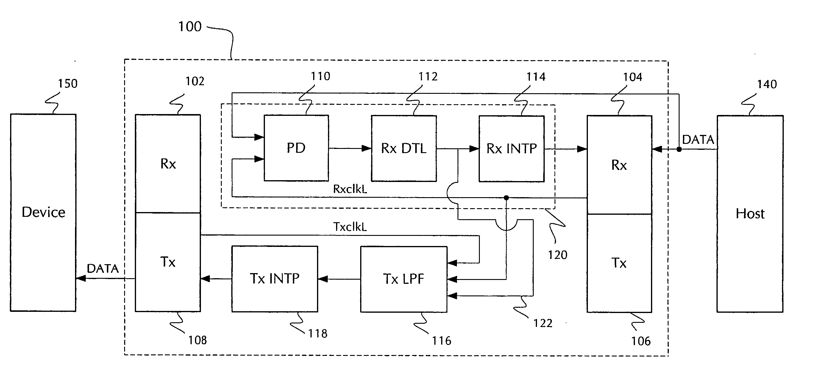
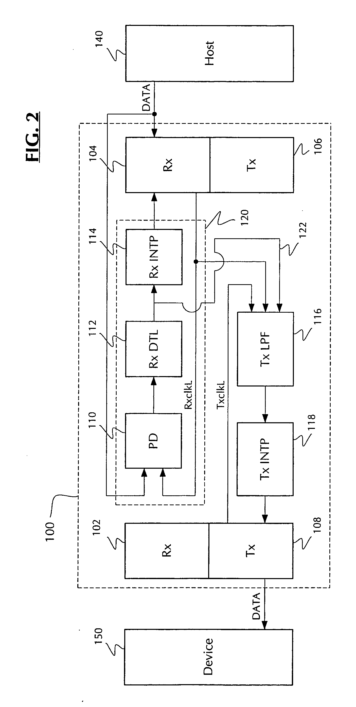
[0015] Reference will now be made in detail to the preferred embodiments of the invention, examples of which are illustrated in the accompanying drawings. While the invention will be described in conjunction with the preferred embodiments, it will be understood that they are not intended to limit the invention to these embodiments. On the contrary, the invention is intended to cover alternatives, modifications and equivalents, which may be included within the spirit and scope of the invention as defined by the appended claims. Furthermore, in the following detailed description of the present invention, numerous specific details are set forth in order to provide a thorough understanding of the present invention. However, it will be readily apparent to one skilled in the art that the present invention may be practiced without these specific details. In other instances, well-known methods, procedures, components, and circuits have not been described in detail so as not to unnecessarily...


PUM


Abstract

Circuits, architectures, systems and methods for facilitating data communications and/or reducing latency in data communications. The architecture includes a clock recovery loop receiving data from a host device and providing a recovered clock signal, a filter circuit receiving recovered clock signal information and providing a control signal that adjusts the transmitter clock in response to recovered clock signal information and the two clock signals, and a transmitter receiving the control signal and transmitting data to a destination device in accordance with the transmitter clock. The circuitry generally includes a clock alignment block receiving first and second periodic signals and providing a control signal in response thereto, a filter for first periodic signal information, and a logic circuit configured to combine the control signal and the filtered information, thereby providing an adjustment signal for the second periodic signal. The systems generally relate to those that include the present architecture and/or circuit. The method generally includes determining a phase difference between first and second periodic signals, one of the periodic signals being recovered from a data stream; adjusting the other periodic signal in response to the phase difference and filtered information from the recovered periodic signal; and transmitting the data stream in accordance with said adjusted periodic signal. The present invention advantageously eliminates a FIFO memory in the data path, thereby reducing transceiver latency and improving system performance.

Description

FIELD OF THE INVENTION [0001] The present invention generally relates to the field of data communications. More specifically, embodiments of the present invention pertain to architectures, circuitry, systems and methods for reducing latency in data communications. DISCUSSION OF THE BACKGROUND [0002]FIG. 1 shows a conventional repeater architecture 10. Repeater 10 is configured to receive and transmit serial data streams between two clock domains in a network. Host 20 is the source of a serial data stream DATA, and device 30 is the destination of the serial data stream DATA. Host 20 operates in a first clock domain having a first frequency f1, repeater 10 operates in a second clock domain having a second frequency f2, and device 30 operates in a third clock domain having a third frequency f3. [0003] Repeater 10 generally includes a first receiver 12 for receiving serial data stream DATA from host 20, a first transmitter 14 for transmitting serial data stream DATA to device 30, and a ...

Claims


Application Information

Patent Timeline
IPC IPC(8): G06F1/04G06F13/40
CPCG06F13/405
Inventor SUTARDJA, PANTASWU, LEISHENG, HONGYING
Owner MARVELL ASIA PTE LTD
Why Eureka
Try Eureka