Preparing preforms for fibre fabrication

a technology of preforms and optical fibres, applied in the field of producing preforms for optical fibres, can solve the problems of restricted preform size, poor heat conductivity of the material from which optical fibres are typically manufactured, etc., and achieve the effect of increasing the length of optical fibres, reducing the number of fibre connections necessary, and increasing the size and volum

Inactive Publication Date: 2005-02-17
SYDNEY THE UNIV OF +2
View PDF1 Cites 6 Cited by
  • Summary
  • Abstract
  • Description
  • Claims
  • Application Information

AI Technical Summary

Benefits of technology

[0015] Advantageously, the holes in the preform serve not only their ultimate functional purpose in the optical fibre, but also serve as conduits for the heating fluid in the preform. This assists in achieving a suitable temperature gradient across the cross-section of the preform for drawing of the preform.
[0016] Another surprising advantage has arisen from the present invention insofar as the invention has permitted the use of relatively large preforms (that is, preforms of 50 mm diameter or greater) in comparison with conventional preforms. The preform is heated by the aforementioned technique, and then drawn. This provides a number of significant advantages over the prior art. For example, the increase in size and volume of the preform increases the length of optical fibre which can be ultimately dra...

Problems solved by technology

However, the materials from which optical fibres are typically manufactured are poor heat conductors.
This results in a temperature gradient across the...

Method used


Image

  • Preparing preforms for fibre fabrication
  • Preparing preforms for fibre fabrication
  • Preparing preforms for fibre fabrication

Examples


Embodiment Construction

[0029] A number of preferred aspects of the invention will now be described, by way of example only.

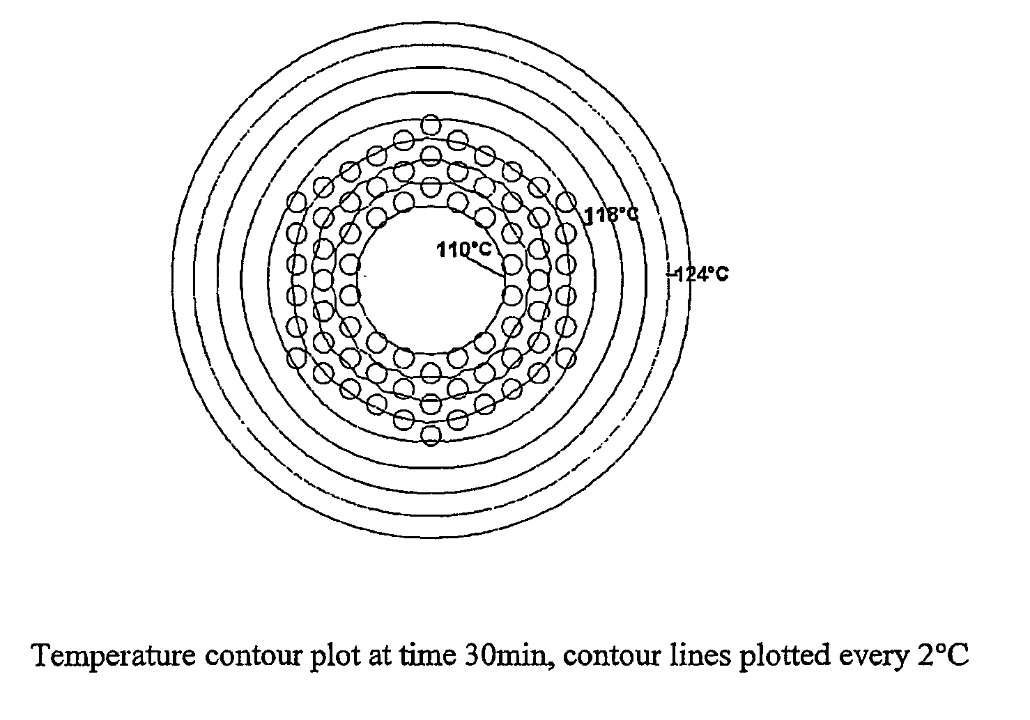
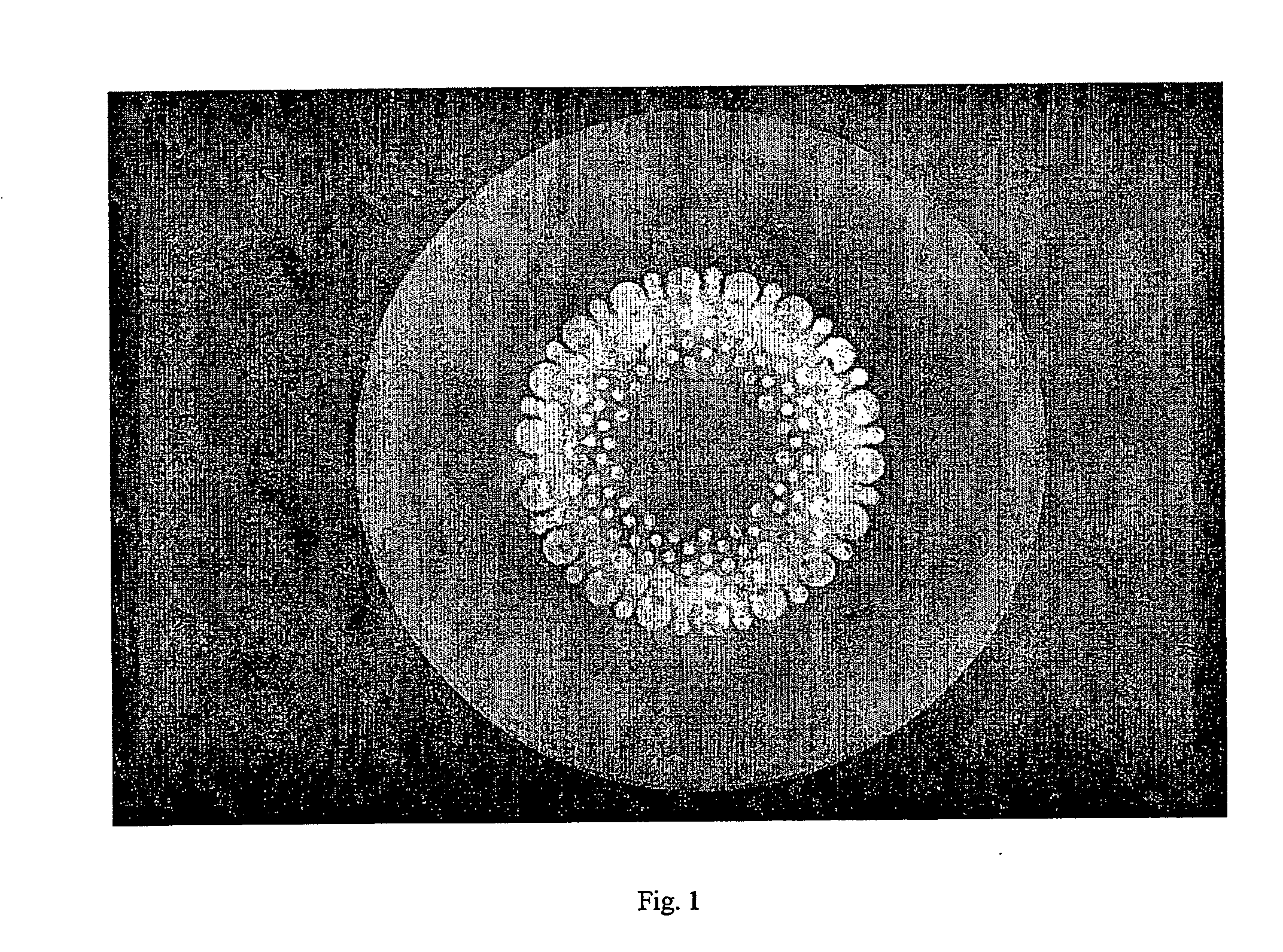
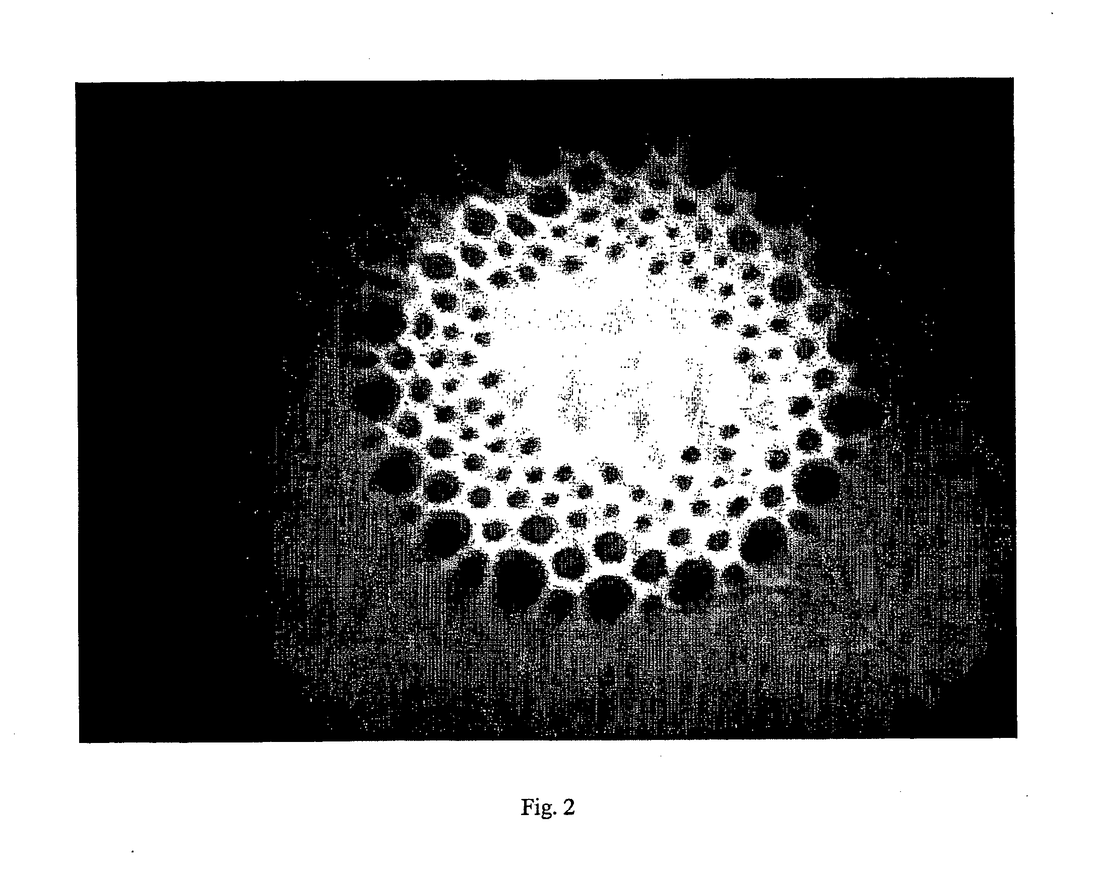
[0030] In one embodiment of the invention the preform includes a plurality of holes so as to permit ingress of a heated fluid to heat the interior of the preform. In one preferred embodiment the holes in the preform have parallel axes and extend parallel to the principal axis of the preform. It is further preferable for the holes to extend through the preform. In such an embodiment, the heated fluid can pass through the preform so as to heat the interior of the preform.

[0031] In another embodiment of the invention, the holes in the preform may be heated by pins or protrusions instead of heated air or other fluid. In this embodiment, the pins are heated and inserted into the holes in the preform to produce the desired temperature gradient across the preform to facilitate the subsequent drawing process. In one embodiment, such pins or protrusions can form part of a mould in which the ...


PUM

PropertyMeasurementUnit
Diameteraaaaaaaaaa
Densityaaaaaaaaaa
Temperatureaaaaaaaaaa

Abstract

This invention relates to a method of producing a preform for an optical fibre. More particularly, the present invention relates to a method of preparing preforms for the production of holey optical fibres. The invention provides a method of producing an optical fibre, said method comprising applying heat to the interior of a preform and subsequently drawing said optical fibre from said preform. The invention also provides a method of producing an optical fibre, said method comprising preparing a preform comprising a body of optically suitable material and removing material at predetermined locations in the body so as to provide a plurality of holes within the body, applying heat to the interior of the preform and subsequently drawing said optical fibre from said preform.

Description

FIELD OF THE INVENTION [0001] This invention relates to a method of producing a preform for an optical fibre. More particularly, the present invention relates to a method of preparing preforms for the production of holey optical fibres. Whilst the invention has particular application in the manufacture of optical fibre from polymer or glass materials, it should be appreciated that the invention can be applied in producing optical fibre from any form of suitable material. BACKGROUND TO THE INVENTION [0002] Any discussion of the prior art throughout the specification should in no way be considered as an admission that such prior art is widely known or forms part of common general knowledge in the field. [0003] Glass Microstructured Optical Fibres (MOFs) (also known as “photonic crystal fibres” or “holey fibres”) were first developed in 1974 by Bell labs. They have attracted much more attention since 1996 when a group from the University of Bath published a paper on an “endlessly” sing...

Claims


Application Information

Patent Timeline
IPC IPC(8): B29D11/00C03B37/012G02B6/02G02B6/032
CPCB29D11/00721C03B37/0122C03B37/01231C03B37/01268G02B6/02371C03B2203/14C03B2203/42G02B6/02357G02B6/02361C03B37/02781Y02P40/57
Inventor LARGE, MARYANNE CANDIDA JANEARGYROS, ALEXANDERZAGARI, JOSEPHMAXWELL, IAN ANDREWEIJKELENBORG, MARTIJN ALEXANDER VANISSA, NADER
Owner SYDNEY THE UNIV OF
Why Eureka
Try Eureka