
Electroosmotic micropumps with applications to fluid dispensing and field sampling

a technology of electroosmotic pumps and fluid dispensing, which is applied in the direction of positive displacement liquid engines, laboratory glassware, instruments, etc., can solve the problems of inability to generate pressure and/or flow in a compact and reliable device, and achieve high flow rate, high pressure, and improved performance.

Inactive Publication Date: 2005-02-17
THE BOARD OF TRUSTEES OF THE LELAND STANFORD JUNIOR UNIV
View PDF47 Cites 44 Cited by
  • Summary
  • Abstract
  • Description
  • Claims
  • Application Information

AI Technical Summary

Benefits of technology

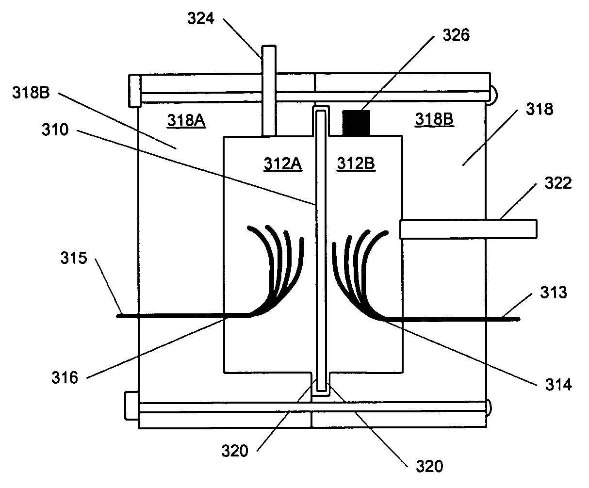
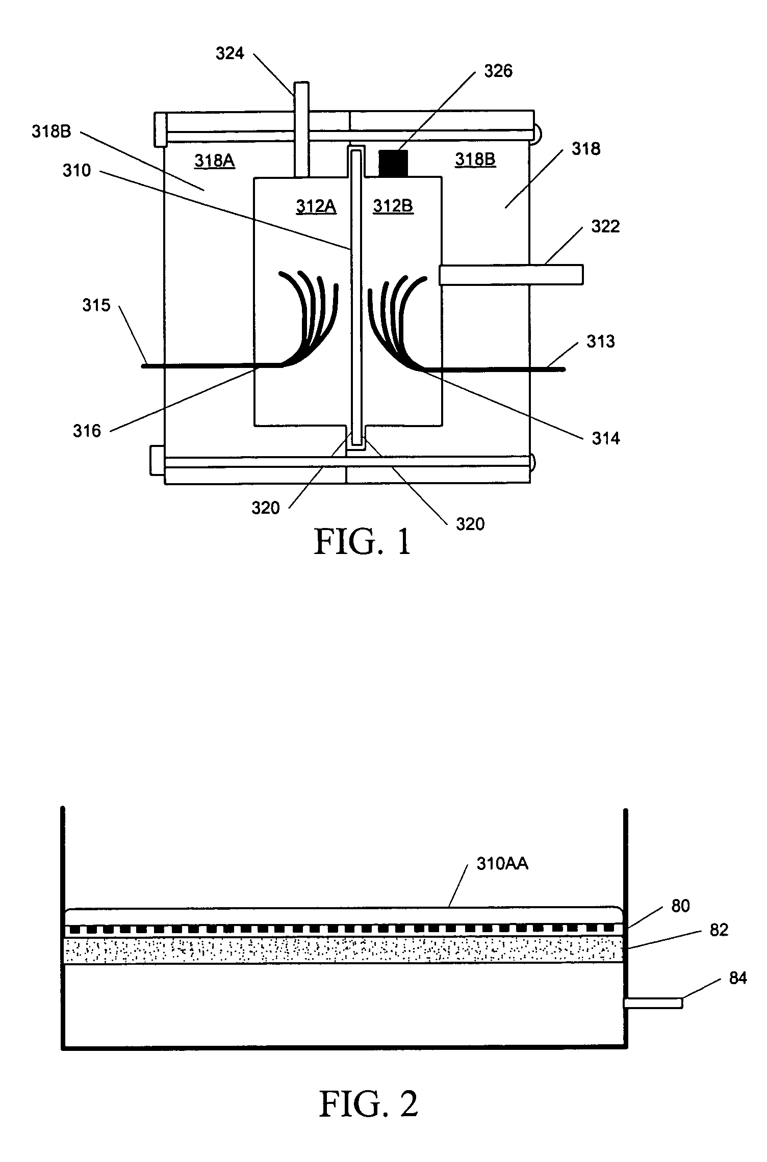
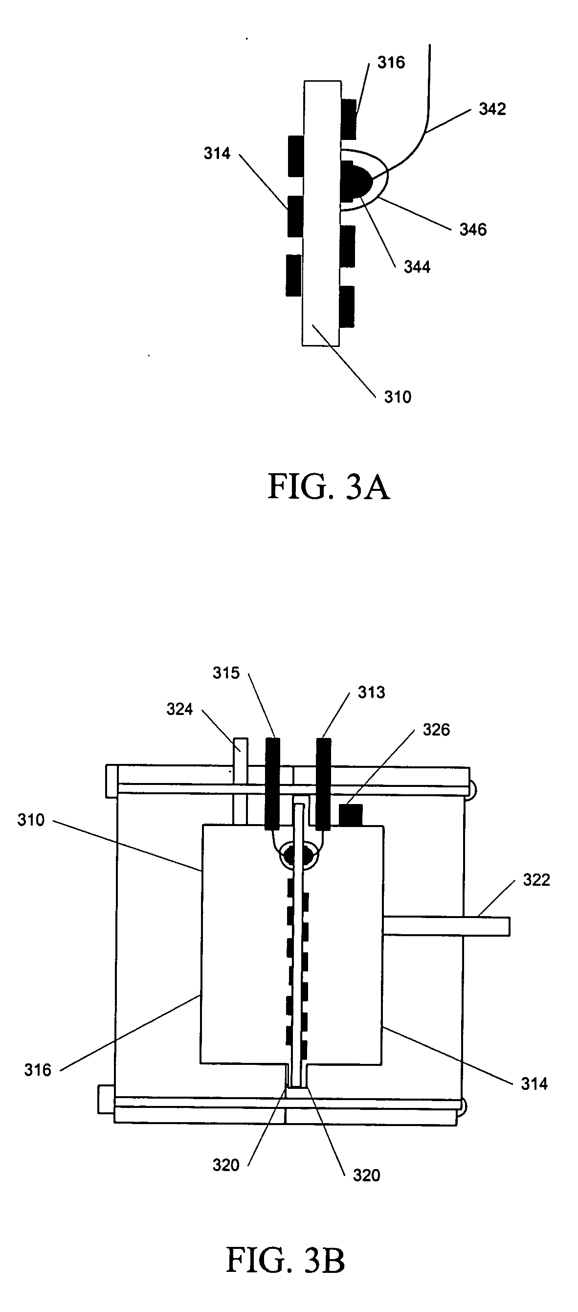
"The present invention describes an apparatus and methods that use electroosmotic pumps to generate high pressure and flow without moving mechanical parts. These pumps offer advantages over currently available micropumps as they have higher pressure capacity, reduced noise, and improved performance and efficiency. The invention also includes a solid-state pipettor that replaces manual and automatic pipettes, a field sampling device that combines pumping and filtering applications, and a pre-concentration method for uses such as a portable environmental monitoring system. The invention offers precise metering of liquid samples and offers a small footprint for use in various applications."

Problems solved by technology

These pumps, to date, appear to be incapable of generating the pressure and / or flow in a compact and reliable device.

Method used


Image

  • Electroosmotic micropumps with applications to fluid dispensing and field sampling
  • Electroosmotic micropumps with applications to fluid dispensing and field sampling
  • Electroosmotic micropumps with applications to fluid dispensing and field sampling

Examples


Embodiment Construction

[0038] The following description of the invention is provided as an enabling teaching of the invention and its best, currently known embodiment. Those skilled in the art will recognize that many changes can be made to the embodiments described while still obtaining the beneficial results of the present invention. It will also be apparent that some of the desired benefits of the present invention can be obtained by selecting some of the features of the present invention without utilizing other features. Accordingly, those who work in the art will recognize that many modifications and adaptations of the invention are possible and may even be desirable in certain circumstances and are part of the present invention. Thus, the following description is provided as illustrative of the principles of the invention and not in limitation thereof since the scope of the present invention is defined by the claims.

[0039] Various figures show different aspects of the system, and, where appropriate...


PUM

PropertyMeasurementUnit
flow ratesaaaaaaaaaa
flow rateaaaaaaaaaa
diameteraaaaaaaaaa

Abstract

Apparatus and methods according to the present invention preferably utilize electroosmotic pumps in fluid handling and field sampling applications. The electroosmotic pumps used in these applications are capable of generating high pressure and flow without moving mechanical parts and the associated generation of unacceptable electrical and acoustic noise, as well as the associated reduction in reliability. Having multiple small flow channels in parallel provides both a high flow rate and high pressure in liquid handling. These electroosmotic pumps are fabricated with materials and structures that improve performance, efficiency, and reduce weight and manufacturing cost relative to presently available micropumps. These electroosmotic pumps also allow for recapture of evolved gases and deposited materials, which may provide for long-term closed-loop operation. Apparatus and methods according to the present invention also allow active regulation of the fluid handling and field sampling devices through electrical control of the flow through the pump. Electroosmotic pumping enables precise dispensing of samples to form genetic, proteomic, or small molecule arrays. A fluid sensor which can be optical, capacitive or other type of electrical sensor is integrated with the electroosmotic pump for measuring liquid levels in liquid drawing and dispensing operations.

Description

CROSS REFERENCE TO RELATED APPLICATIONS [0001] This application is related to, and contains common disclosure with, co-pending and commonly assigned patent applications “Electroosmotic Microchannel Cooling System” Ser. No. 10 / 053,859, filed Jan. 19, 2002; and “Control of Electrolysis Gases in Electroosmotic Pump Systems”, Ser. No. 10 / 272,048, filed Oct. 16, 2002, which is a continuation-in-part of application Ser. No. 10 / 053,859. Each co-pending application is hereby incorporated by reference into this description as filly as if here represented in full.[0002] The inventions described herein were supported in part by DARPA / Air Force Contract F33615-99-C-1442.FIELD OF THE INVENTION [0003] This invention relates generally to fluid dispensing and field sampling. Specifically, this invention relates to drawing and dispensing fluids and filtering field samples using electroosmotic pumps. BACKGROUND OF THE INVENTION [0004] There has been extensive research into the development of micropum...

Claims


Application Information

Patent Timeline
Patent Type & Authority Applications(United States)
IPC IPC(8): B01L3/02C01B5/00F04B19/00
CPCB01L3/0241B01L2200/143F04B19/006B01L2400/0418C01B5/00B01L2300/069
Inventor HUBER, DAVIDYAO, SHUHUAISANTIAGO, JUAN G.
Owner THE BOARD OF TRUSTEES OF THE LELAND STANFORD JUNIOR UNIV
Learn More