Transfer out device

a technology of transfer device and transfer device, which is applied in the direction of gas current separation, pile separation, solid separation, etc., can solve the problems of long time-consuming, complicated design, and inability to produce, and achieve the effect of reliable operation and cheap production

Active Publication Date: 2005-02-17
MULLER MARTINI HLDG
View PDF19 Cites 46 Cited by
  • Summary
  • Abstract
  • Description
  • Claims
  • Application Information

AI Technical Summary

Benefits of technology

[0007] It is therefore the object of the present invention to create a transfer out device of the aforementioned type which can be produced cheaply and is nevertheless operatively sound. The transfer out device must operate reliably even i

Problems solved by technology

Transfer out devices of the aforementioned type have been known for a long time.
Since the thicknesses of the printed products, generally stacks of several printed sheets, can vary considerab

Method used


Image

  • Transfer out device
  • Transfer out device
  • Transfer out device

Examples


Embodiment Construction

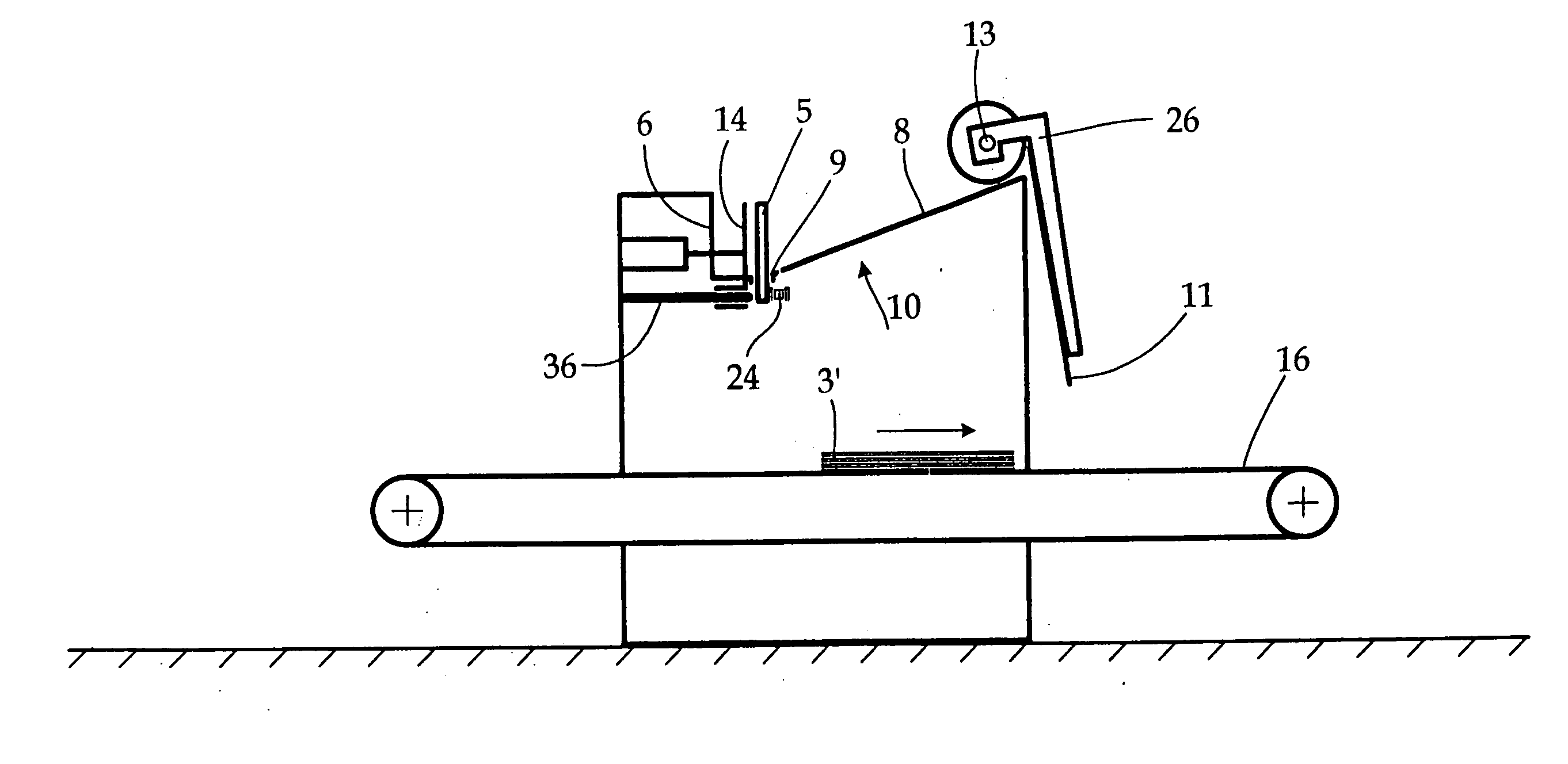
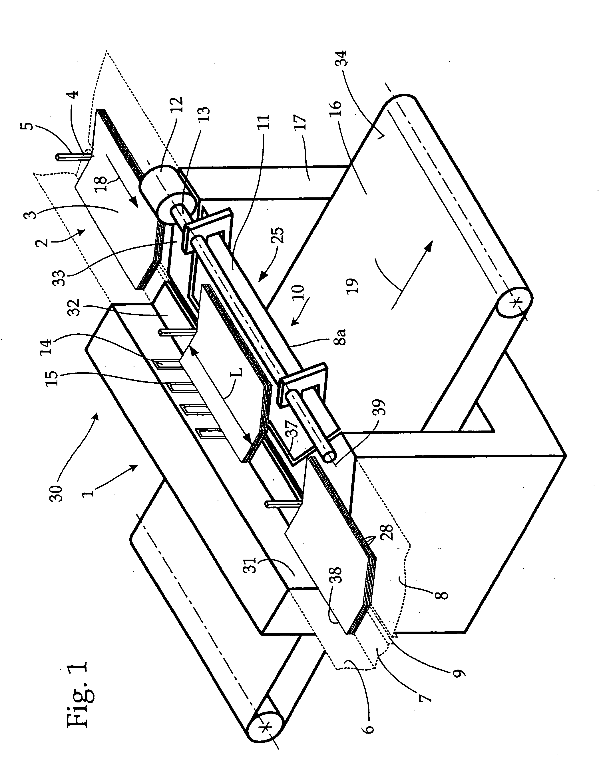
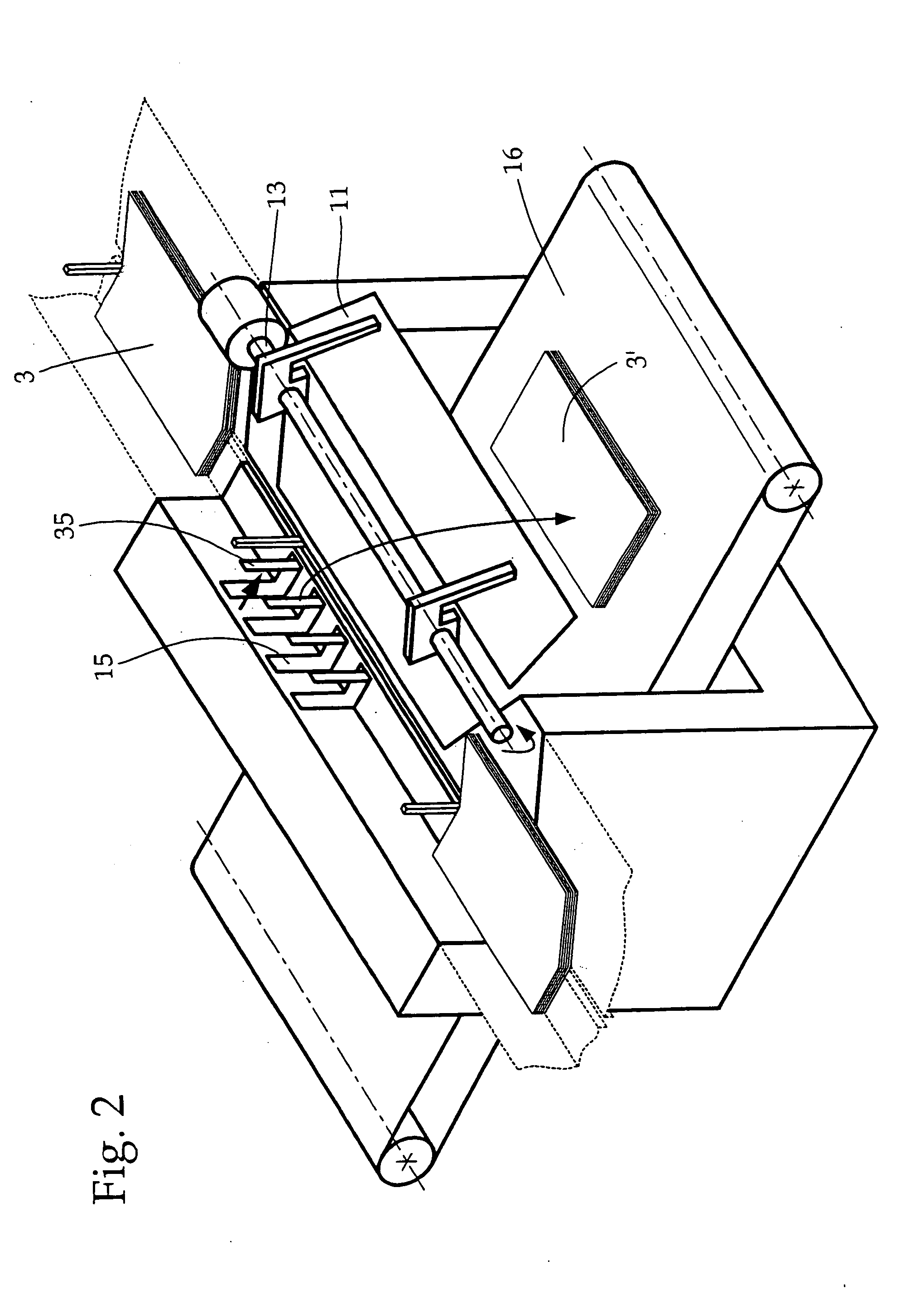
[0024]FIG. 1 shows a segment of a gathering and collating machine 30, known per se, provided with a transport channel 2 in which printed products 3 are transported continuously in a clocked flow in the direction of arrow 18. A transport device 4, for example, is used for the transporting in a known manner, wherein the transport device has several finger-shaped pushers, or driving pins, 5 that move the printed products 3 inside the transport channel 2. According to FIG. 5, the pushers 5 are mounted on an endless chain 24 and project upward through a slot 9 into the transport channel.

[0025] The printed products 3 are, in particular, stacks of folded sheets 28, for example, used for producing books in a perfect binder, installed downstream, that is not shown herein. The back length of the printed products 3 is given the reference L in FIG. 1. The thickness of the printed products 3 and / or the stack can vary considerably, wherein a printed product 3 can also be a single sheet 28. Durin...


PUM


Abstract

A device to transfer printed products out of the transport channel of a gathering and collating machine in which the printed products are transported in a clocked flow comprises an arrangement for transferring the printed products in a downward direction out of the transport channel. The printed products are preferably removed through an opening in a bottom part of the transport channel, wherein the opening is provided with a flap that can be pivoted downward and away from a product guide wall of the transport channel for the transfer out of a printed product.

Description

CROSS-REFERENCE TO RELATED APPLICATION [0001] This application claims the priority of European Patent Application No. 03405461.9, filed on Jun. 25, 2003, the subject matter of which is incorporated herein by reference. BACKGROUND OF THE INVENTION [0002] The invention relates to a device for transferring printed products out of the transport channel of a gathering and collating machine in which the printed products are moved along in a timed flow. [0003] Transfer out devices of the aforementioned type have been known for a long time. They are used to transfer printed products that are defective or used for control purposes out of the transport channel and, in particular, to pull stacks or individual sheets from the timed flow without interrupting the production. With this type of transfer out device, the printed products are generally transferred out of the transport channel either perpendicular to the printed product in an upward direction, or parallel to the surface of the printed ...

Claims


Application Information

Patent Timeline
IPC IPC(8): B42C19/08B65G11/12B41F13/54B65G47/53B65H29/60B65H29/62
CPCB65H29/62
Inventor GROB, MATHIAS
Owner MULLER MARTINI HLDG
Why Eureka
Try Eureka