Laser irradiation method, laser irradiation apparatus, and method of manufacturing a semiconductor device

a laser irradiation and semiconductor technology, applied in the direction of laser beam welding apparatus, manufacturing tools, solid-state devices, etc., can solve the problems of difficult optical adjustment of an optical system as such, inability to uniformly anneal the irradiation object, and fluctuation among the tfts on the same substrate, so as to improve the operation characteristic and reliability of the semiconductor device, and reduce the fluctuation of the electric characteristic of the tfts. , the effect o

Active Publication Date: 2005-02-17
SEMICON ENERGY LAB CO LTD
View PDF28 Cites 20 Cited by
  • Summary
  • Abstract
  • Description
  • Claims
  • Application Information

AI Technical Summary

Benefits of technology

[0017] The present invention is characterized in that laser beams emitted from a plurality of lasers are each divided and that laser beams emitted from different lasers and having different energy distributions are synthesized to form laser light having excellent uniformity in energy distribution. Here, energy distributions which are not identical but become the same distribution by rotation are deemed as different energy distributions. Also, the present invention is characterized in that laser beams emitted from a plurality of lasers are each divided, and that a laser beam including at least one laser beam that is emitted from a different laser and is in a different positional relation is synthesized with another such laser beam to form laser light having excellent uniformity in energy distribution.
[0018] Also, the present invention is characterized in that laser beams emitted from a plurality of lasers are each divided, and that laser beams emitted from different lasers and having different energy distributions enter a convex lens at an angle, exit the convex lens, and are synthesized on an irradiation surface or in the vicinity thereof to form rectangular laser light having excellent uniformity in energy distribution.
[0021] When a divided laser beam is overlapped with another divided laser beam, it is preferred to overlap laser beams having different energy distributions from one another. This is because overlapping a large number of laser beams that have different energy distributions produces uniform laser light.
[0033] In the above structure, the semiconductor film is desirably a film containing silicon. A glass substrate, a quartz substrate, a silicon substrate, a plastic substrate, a metal substrate, a stainless steel substrate, a flexible substrate, etc. can be used as a substrate on which the semiconductor film is formed. Examples of the glass substrate include a barium borosilicate glass substrate and an aluminoborosilicate glass substrate. A flexible substrate means a substrate in the form of a PET, PES, PEN, or acrylic film or other similar film. When a flexible substrate is used to manufacture a semiconductor device, the device can have a reduced weight. It is desirable to form on the front side, or on the front side and back side, of a flexible substrate a single layer or multi-layer of aluminum films (AlON, AlN, AlO, or the like), carbon films (DLC (diamond-like carbon) or the like), or SiN films as a barrier layer because the barrier layer improves the durability and other properties.
[0034] The present invention synthesizes laser beams emitted from different lasers on an irradiation surface or in the vicinity thereof and therefore interference does not take place. Most desirably, laser beams having different energy distributions from one another are synthesized on an irradiation surface or in the vicinity thereof. However, since the optimum synthesizing method varies from one laser light mode to another, the synthesizing method used can be chosen to suit individual cases. For example, laser light in the TEMoo mode is highly symmetrical and therefore laser light having a relatively high uniformity can be obtained by dividing laser light into two and synthesizing the left half and right half thereof. Needless to say, more highly uniform laser light is obtained when the number of division is larger. Laser light in other modes can also provide highly uniform laser light using the same method.
[0035] The present invention can irradiate a semiconductor film formed on a substrate with a rectangular beam having highly uniform energy distribution. Accordingly, a semiconductor film of uniform physical property can be obtained. This makes it possible to reduce fluctuation in electric characteristic of TFTs manufactured from this semiconductor film. This also improves the operation characteristic and reliability of a semiconductor device manufactured from these TFTs.

Problems solved by technology

Even when the laser light scans an irradiation object for annealing in a manner that makes the attenuation regions overlap each other, it still is impossible to anneal the irradiation object uniformly because annealing conditions of the attenuation region are entirely different from annealing conditions of the highly uniform region.
Therefore, if this semiconductor film varied in crystallinity from one region to another is used to manufacture TFTs, the electric characteristic of a TFT formed from the region that is annealed by the attenuation region is inferior to other TFTs and causes fluctuation among the TFTs on the same substrate.
Optical adjustment for an optical system as such is very difficult to perform and, in addition, the apparatus has to be large in size because of large footprint.

Method used


Image

  • Laser irradiation method, laser irradiation apparatus, and method of manufacturing a semiconductor device
  • Laser irradiation method, laser irradiation apparatus, and method of manufacturing a semiconductor device
  • Laser irradiation method, laser irradiation apparatus, and method of manufacturing a semiconductor device

Examples


embodiment

[0062] Embodiment Mode 1

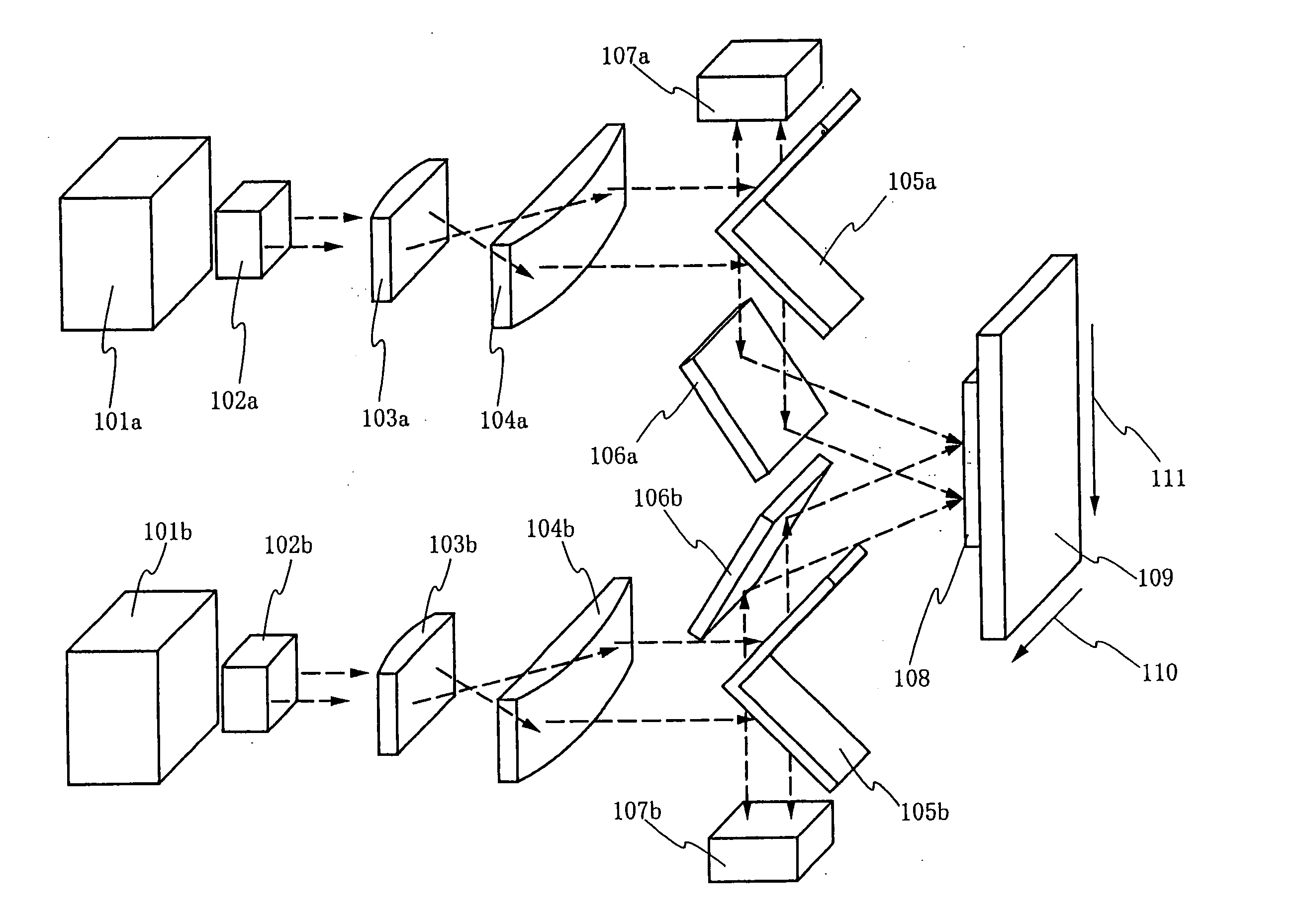
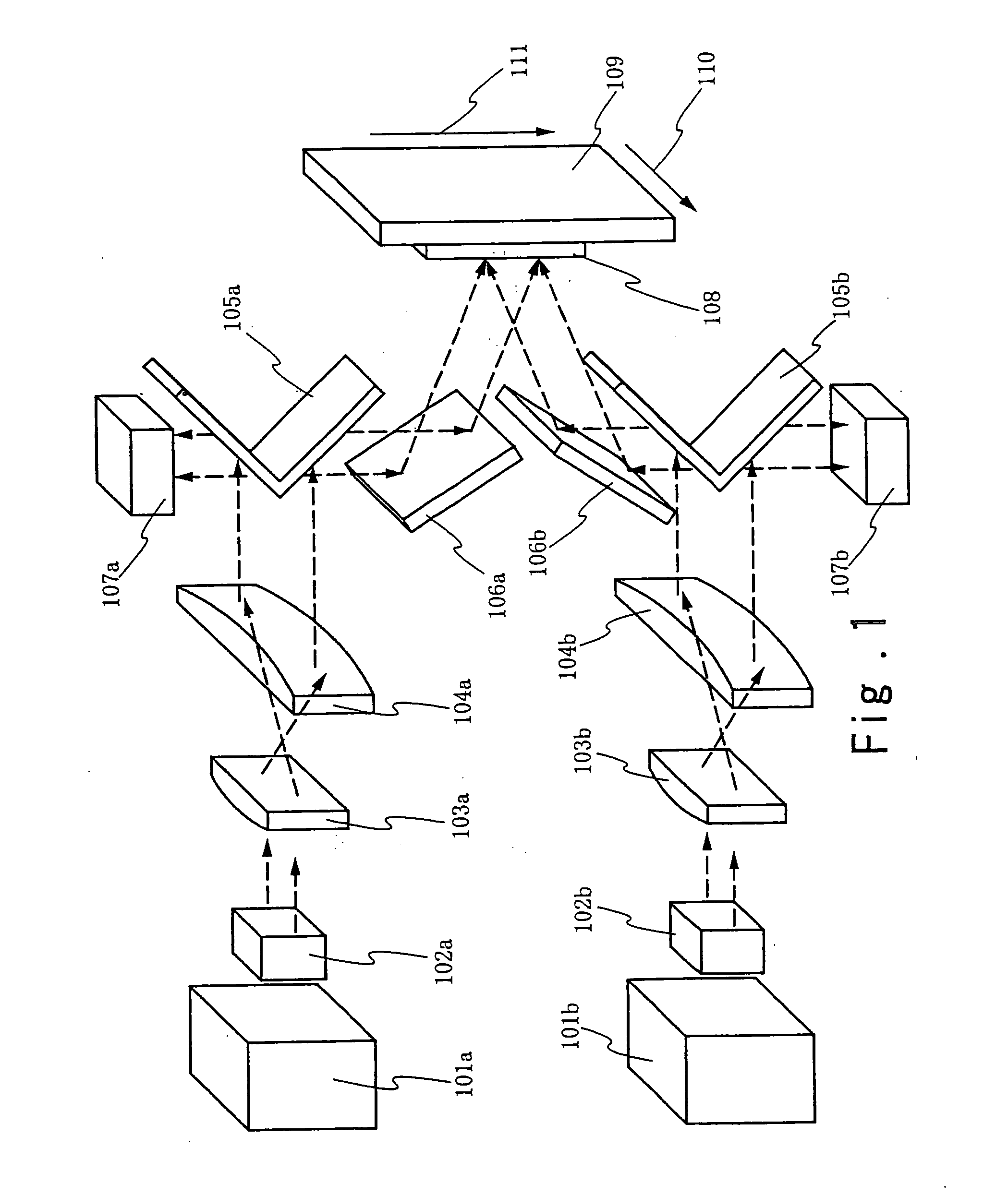
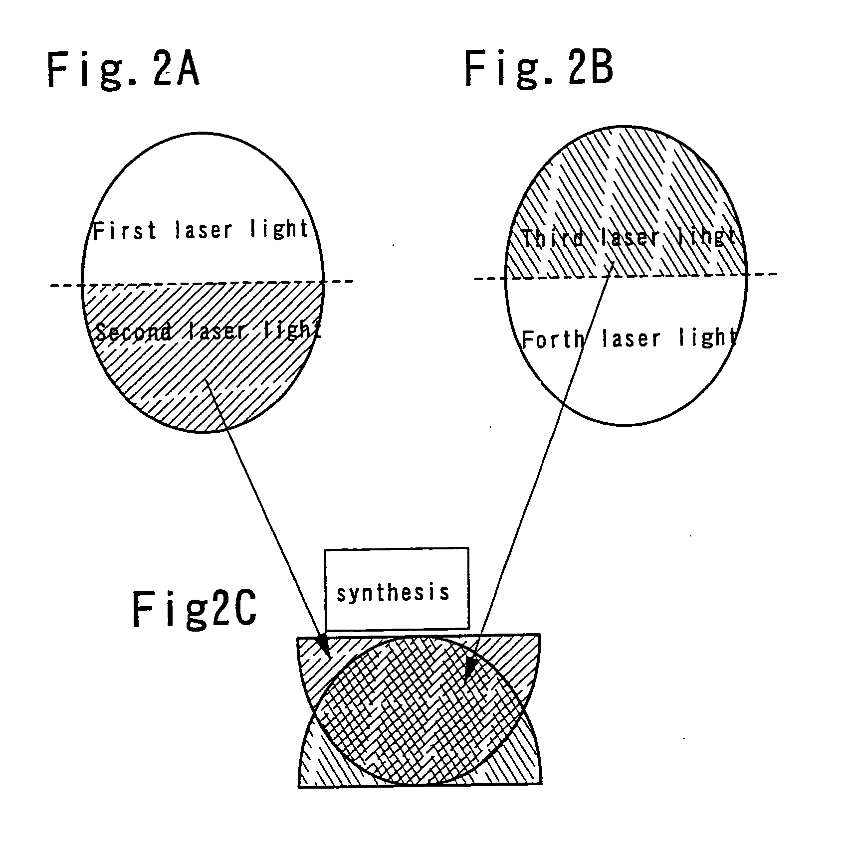
[0063] This embodiment mode describes with reference to FIG. 1 and FIGS. 2A to 2C an example of optical system for dividing laser beams that are emitted from a plurality of lasers and overlapping laser beams that have different energy distributions from one another.

[0064] A laser 101a and a laser 101b each emit laser light. The lasers 101a and 101b used here are continuous wave or pulse oscillation solid-state lasers, gas lasers, or metal lasers. Examples of the solid-state lasers include a continuous wave or pulse oscillation YAG laser, YVO4 laser, YLF laser, YAlO3 laser, Y2O3 laser, glass laser, ruby laser, alexandrite laser, and Ti:sapphire laser. Examples of the gas lasers include a continuous wave or pulse oscillation excimer laser, Ar laser, Kr laser, and CO2 laser. Examples of the metal lasers include a continuous wave or pulse oscillation helium cadmium laser, copper steam laser, and gold steam laser. The laser light emitted from the lasers 101a and ...

embodiment 1

[0095] Embodiment 1

[0096] This embodiment describes with reference to FIG. 3 and FIGS. 4A to 4E an example of optical system for dividing laser beams that are emitted from four lasers and overlapping laser beams that have different energy distributions from one another.

[0097] Lasers 131a to 131d each emit laser light. The lasers 131a to 131d used here are continuous wave or pulse oscillation solid-state lasers, gas lasers, or metal lasers. Examples of the solid-state lasers include a continuous wave or pulse oscillation YAG laser, YVO4 laser, YLF laser, YAlO3 laser, Y2O3 laser, glass laser, ruby laser, alexandrite laser, and Ti:sapphire laser. Examples of the gas lasers include a continuous wave or pulse oscillation excimer laser, Ar laser, Kr laser, and CO2 laser. Examples of the metal lasers include a continuous wave or pulse oscillation helium cadmium laser, copper steam laser, and gold steam laser. The laser light emitted from the lasers 131a to 131d may be converted into harmo...

embodiment 2

[0108] Embodiment 2

[0109] This embodiment describes with reference to FIG. 6 an example of optical system for dividing laser beams that are emitted from three lasers and overlapping laser beams that have different energy distributions from one another.

[0110] Lasers 121a to 121c each emit laser light. The lasers 121a to 121c used here are continuous wave or pulse oscillation solid-state lasers, gas lasers, or metal lasers. Examples of the solid-state lasers include a continuous wave or pulse oscillation YAG laser, YVO4 laser, YLF laser, YAlO3 laser, Y2O3 laser, glass laser, ruby laser, alexandrite laser, and Ti:sapphire laser. Examples of the gas lasers include a continuous wave or pulse oscillation excimer laser, Ar laser, Kr laser, and CO2 laser. Examples of the metal lasers include a continuous wave or pulse oscillation helium cadmium laser, copper steam laser, and gold steam laser. The laser light emitted from the lasers 121a to 121c may be converted into harmonic by a non-linea...


PUM

PropertyMeasurementUnit
aspect ratioaaaaaaaaaa
sizeaaaaaaaaaa
sizeaaaaaaaaaa

Abstract

In the present invention, each laser light emitted from a plurality of lasers is divided, and laser light including at least one laser light that is emitted from a different laser and that has different energy distribution is synthesized with another such laser light, or laser light including at least one laser light that has different energy distribution is synthesized with another such laser light through a convex lens that is set at an angle to the direction each laser light travels, to form laser light having excellent uniformity in energy distribution.

Description

FIELD OF THE INVENTION [0001] The present invention relates to a laser beam irradiation method and a laser irradiation apparatus for using the method (apparatus including a laser and an optical system for guiding laser beam emitted from the laser to an object to be irradiated). In addition, the present invention relates to a method of manufacturing a semiconductor device, which includes a laser beam irradiation step. Note that a semiconductor device described here includes an electro-optical device such as a liquid crystal display device or a light-emitting device and an electronic device that includes the electro-optical device as a part. DESCRIPTION OF THE RELATED ART [0002] In recent years, a wide study has been made on a technique in which laser annealing is performed for a semiconductor film formed on an insulating substrate made of glass or the like, to crystallize the film, to improve its crystallinity so that a crystalline semiconductor film is obtained, or to activate an im...

Claims


Application Information

Patent Timeline
Patent Type & Authority Applications(United States)
IPC IPC(8): B23K26/067B23K26/073H01L21/77H01L21/84
CPCB23K26/0604B23K26/0608B23K26/067H01L27/1285B23K26/0736B23K26/0738H01L21/02592B23K26/0732
Inventor TANAKA, KOICHIROMORIWAKA, TOMOAKI
Owner SEMICON ENERGY LAB CO LTD
Why Eureka
Try Eureka