
Imaging head with laser diode array and a beam-shaping micro light-pipe array

Inactive Publication Date: 2005-02-17
KODAK IL
View PDF6 Cites 4 Cited by
  • Summary
  • Abstract
  • Description
  • Claims
  • Application Information

AI Technical Summary

Benefits of technology

Another object of the present invention is to provide a multiple laser-beam recording apparatus, which is free of image density irregularities due to non-uniform energy distribution of the LD near field.
Still another object of the present invention is to provide a high energy-efficient multiple laser-beam recording apparatus free of image density irregularities due to non-uniform energy distribution on the LD near field.

Problems solved by technology

The imaging speed in electro-optical plotters is generally limited by the power delivered to the medium by the laser beam(s).
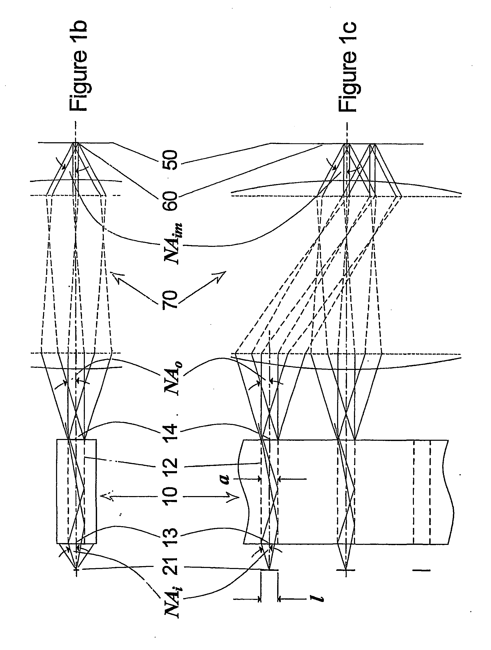
When the image on the photosensitive medium is formed by imaging the near field of the LD, the non-uniform and frequently changing energy distribution of its pattern leads to undesired effects, such as image density irregularities.

Method used


Image

  • Imaging head with laser diode array and a beam-shaping micro light-pipe array
  • Imaging head with laser diode array and a beam-shaping micro light-pipe array
  • Imaging head with laser diode array and a beam-shaping micro light-pipe array

Examples


Embodiment Construction

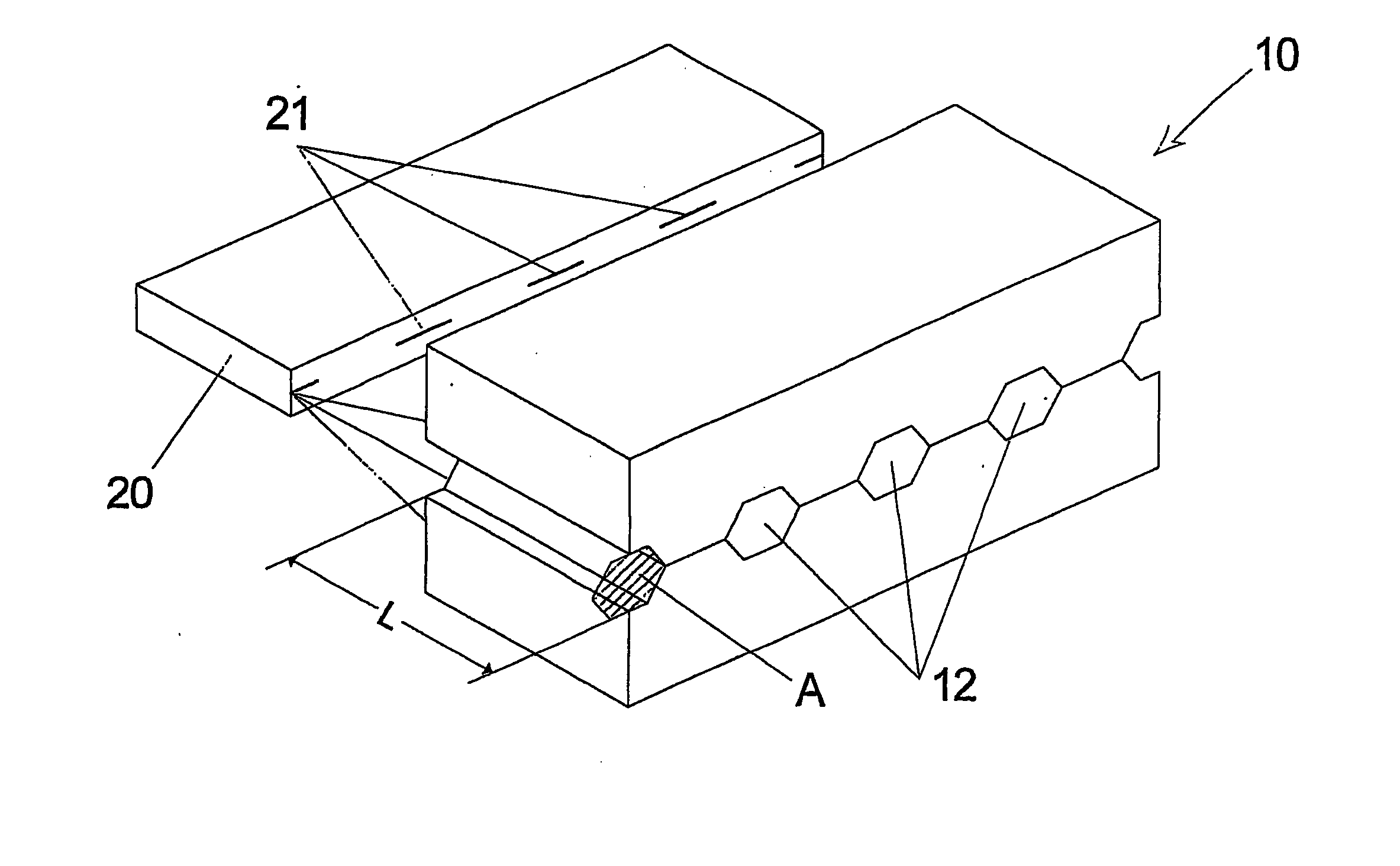
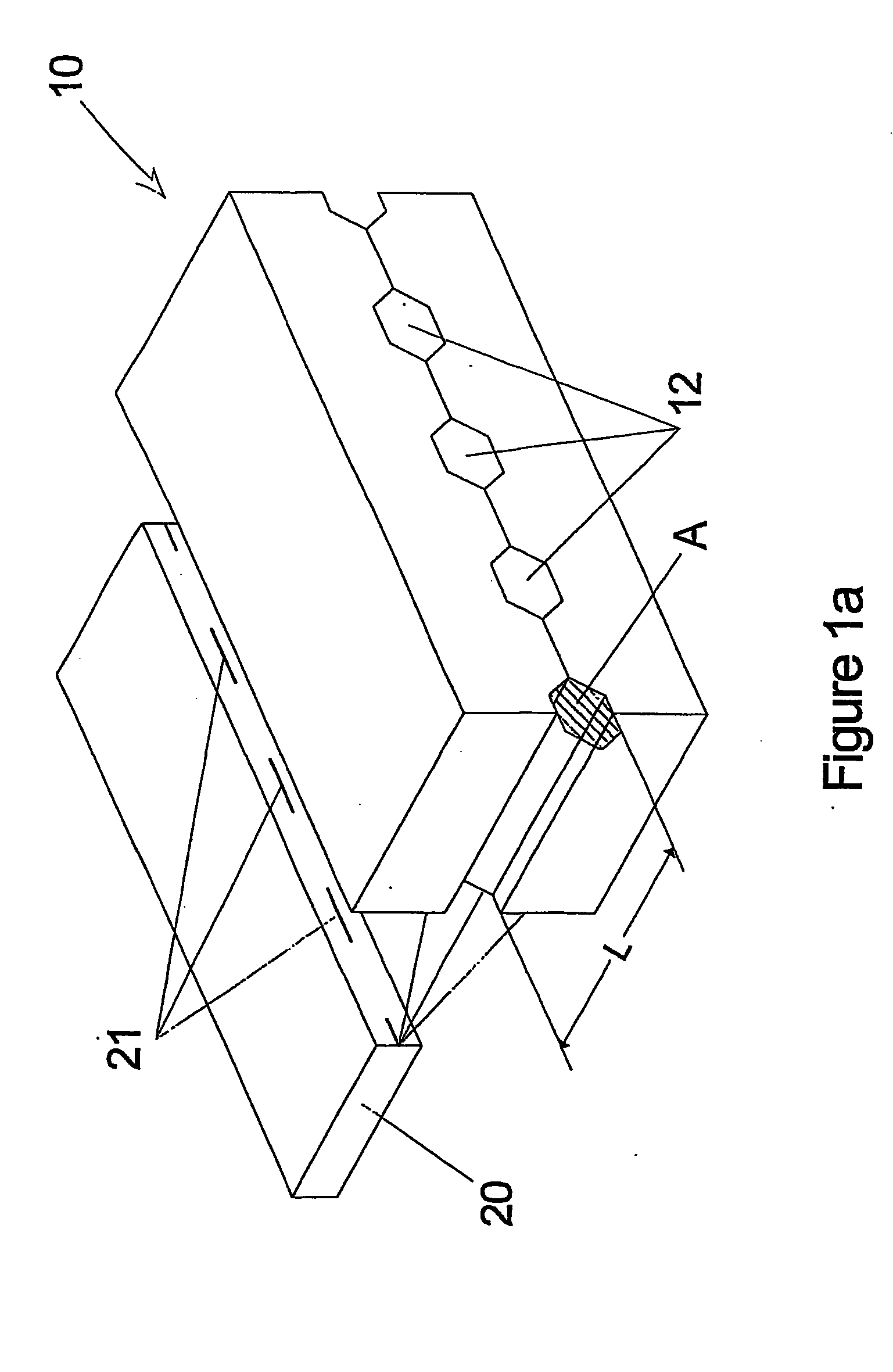
There are generally two types of light-pipes: Bulk and Hollow.

The bulk-type light-pipe is a rod of transparent material with a polygonal cross-section (triangular, rectangular, etc.). The index of refraction of the material forming the light-pipe is higher than the index of refraction of the surrounding material. A typical example is glass rod in air. This type of light-pipes employ the principle of Total Internal Reflection (TIR) on the interface of the two materials—in the above example on the interface glass—air.

The hollow light-pipes are tubes with a polygonal cross section (triangular, rectangular, etc.), made of transparent or nontransparent material, with their internal walls coated with a highly reflective coating. This type of light-pipes work on reflection from the reflective coating.

In all preferred embodiments described below, a hollow light-pipe is taken as an example. It will be, however, appreciated by any person skilled in the art, that same performance can be...


PUM


Abstract

An optical imaging heads that produce a plurality of light spots on light sensitive media such as photographic film or printing plate. The optical head incorporates an array of multi-mode laser diodes as a light source, a Micro Light-Pipe Array (MLPA) as a beam-shaping element, means for reducing the divergence of the laser diode beam in the fast axis direction and means for imaging the laser diode emitters on a surface close to the micro light-pipe entrance aperture.

Description

FIELD OF THE INVENTION The present invention relates to optical imaging heads that produce a plurality of light spots on light sensitive media such as photographic film or printing plate. The optical head incorporates an array of laser diodes as light source and a Micro Light-Pipe Array (MLPA) as a beam-shaping element. BACKGROUND OF THE INVENTION Optical heads for imaging a plurality of light spots on a light sensitive media may incorporate an array of laser diodes as a light source. The laser diodes array may be configured as an ordered plurality of individual laser diodes mounted on a common carriage, or as a plurality of laser emitters manufactured on a single-piece semiconductor material (such as GaAs). For brevity, the light source (whether configured out of individual laser diodes or manufactured on a single semiconductor chip) will be referred to hereunder as Individually Addressed Laser Diode Array (IALDA). The imaging speed in electro-optical plotters is generally limit...

Claims


Application Information

Patent Timeline
IPC IPC(8): B41J2/45G02B3/00G02B3/06G02B6/00G02B6/032G02B6/08G02B6/10G02B6/34G02B6/42G02B27/09
CPCB41J2/451G02B19/0028G02B3/06G02B6/032G02B6/08G02B6/10G02B6/4206G02B6/4249G02B6/425G02B27/09G02B27/0966G02B27/0994G02B2006/0098G02B19/0057G02B3/005
Inventor PILOSSOF, NISSIMKOIFMAN, IGALWEISS, ALEX
Owner KODAK IL
Learn More