Image processing system and vehicle control system

a technology of image processing and vehicle control, applied in the field of image processing system, can solve the problems of difficult differentiation, inability to use the flicker of fluorescent lamps, and insufficient use of traffic lights without fluorescent lamps, and achieve the effects of reducing the influence of noise lights, low cost, and high precision

Active Publication Date: 2005-02-17
HITACHI ASTEMO LTD
View PDF4 Cites 98 Cited by
  • Summary
  • Abstract
  • Description
  • Claims
  • Application Information

AI Technical Summary

Benefits of technology

The invention provides an inexpensive image processing system capable of precisely locating the positions of light spots covering near headlights through far tail lamps by means of one camera. The invention also intends to enhance the vehicle detection performance at night while discriminating the headlights and tail lamps from noise lights such as a traffic light, streetlight, and vending machine, and intends to provide a further advanced function.
The image processing system of the invention photographs plural images while varying the exposure. Thereby, the system is able to detect lights with high precision by using an imaging device having a low dynamic range, and to thereby construct an inexpensive image processing system. Further, the system according to the invention is capable of reducing the influence of noise lights further more, which serves to advance the application that needs the vehicle detection at night by a camera.

Problems solved by technology

However, in case of using a general NTSC camera, the method utilizing the flicker of the fluorescent lamps is not realistic, and it is not totally useful for a traffic light not using a fluorescent lamp.
In view of simply sifting upward, the tail lamps of a bus, which are located at a higher position, show the same behavior; therefore, it is practically difficult to differentiate them.

Method used


Image

  • Image processing system and vehicle control system
  • Image processing system and vehicle control system
  • Image processing system and vehicle control system

Examples


embodiment 1

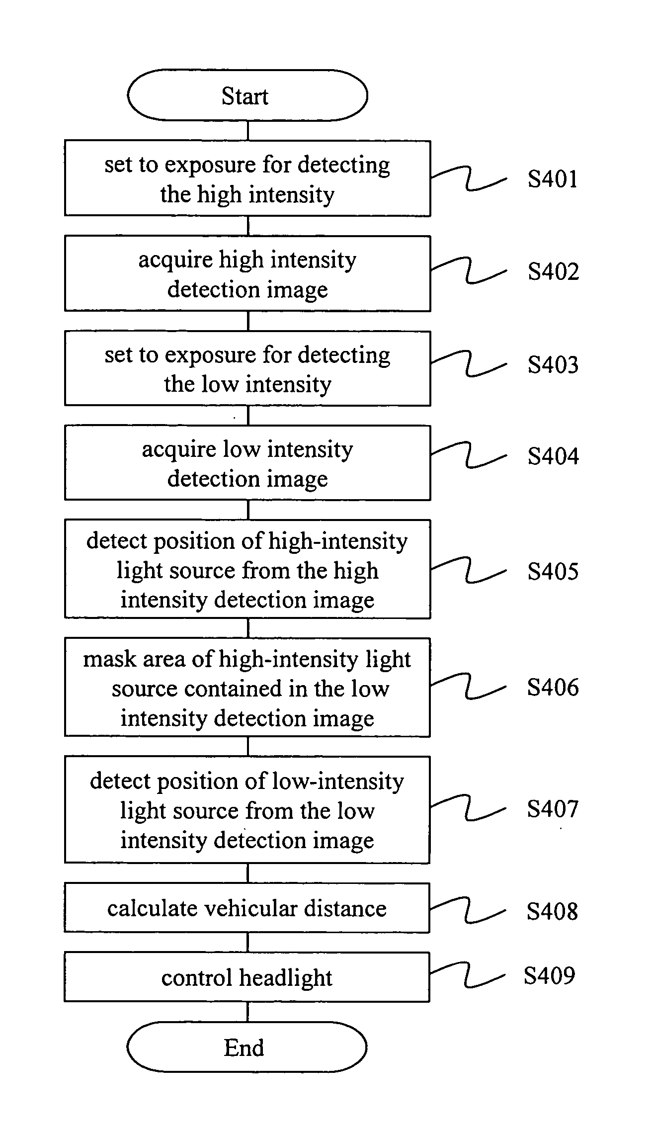
FIG. 4 is a flow chart illustrating the processing flow of the The symbols S401 through S409 each show the step of each processing. First, the outline of each processing step will be explained.

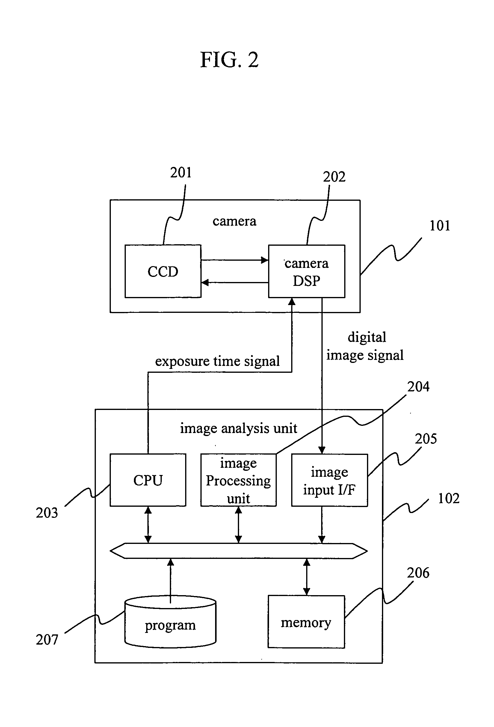
S401 through S404 acquire the high intensity detection image and the low intensity detection image, and transfer them to the image analysis unit 102. The transferred image data contain the synthesizing signals, and the CPU 203 executes the processing related to the image input / output with the synthesizing signals as the interrupt timings.

S405 through S407 detect the positions of the light spots in the images from the image data, using the image analysis unit 102.

S408 calculates the vehicular distance between the own vehicle and the other vehicle traveling in front. S409 calculates the target voltage applied to the headlight 104 on the basis of the vehicular distance to the nearest other vehicle, and the headlight control unit 103 controls the voltage applied to the headlight 104.

Next, ...

embodiment 2

The processing after the calculation of a vehicular distance at S808 is the same as the embodiment 2, and the explanation will be omitted; however, the steps S1501 through S1504 exclude several noise lights, which further enhances the reliability of the light distribution control.

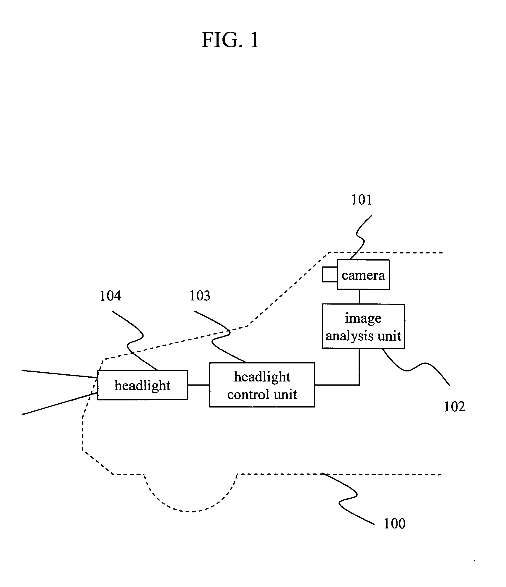
This embodiment, while describing the light distribution control of the headlights, acquires the vehicular distance to a preceding vehicle with high precision even at night. Therefore, this embodiment can be utilized for the control of a follow-up travel to the preceding vehicle, taking the vehicular distance to the preceding vehicle into consideration. FIG. 20 illustrates a configuration of the follow-up travel control. On the basis of the distance to the preceding vehicle and the direction information calculated by the image analysis unit 102 and the speed information by a speed sensor 2007, the speed control to follow the preceding vehicle is executed by controlling an engine 2004, gearbox 2005, and bra...


PUM


Abstract

The invention provides an image processing system capable of precisely locating the positions of the light spots covering near headlights through far tail lamps by using one camera. The invention, discriminating the headlights and tail lamps from noise lights such as a traffic light, streetlight, and vending machine, enhances the vehicle detection performance at night. The system includes an image input means that inputs images in front of a vehicle, an image analysis means that analyzes the images inputted by the image input means. The image input means has a means of photographing more than two images with different exposures. The image analysis means analyzes the images photographed by the image input means to transform them into the position information of the vehicles traveling in front.

Description

FIELD OF THE INVENTION The present invention relates to an image processing system mounted on a vehicle and a vehicle control system. BACKGROUND OF THE INVENTION There is a technique of detecting locations and directions of other vehicles by using images photographed by a camera mounted on a vehicle. The technique detects headlights and tail lamps of the other vehicles at night to generate information of the other vehicles on the basis of the detected information. It is preferable to set the headlights to high beams during traveling at night if there is not a vehicle in front in order to better the visibility of a driver, and to set the headlights to low beams according to the vehicular distance if there is in front. Therefore, it is essential for the technique to detect the distance from the own vehicle to a preceding vehicle in front or an opposing vehicle. As a method of calculating a vehicular distance, the camera mounted on the vehicle photographs the front state of the vehic...

Claims


Application Information

Patent Timeline
Patent Type & Authority Applications(United States)
IPC IPC(8): B60Q1/08B60Q1/14B60R21/00B60Q1/52B60R1/00G06K9/00G06T1/00G06T7/00G08G1/16
CPCB60Q1/1423B60Q9/008B60Q2300/054B60Q2300/3321B60Q2300/41H04N5/2355G01M11/068G06K9/00825G06T7/0042G06T2207/30248B60Q2300/42G06T7/73G06V20/584H04N23/741
Inventor OTSUKA, YUJITAKENAGA, HIROSHIMURAMATSU, SHOJIMONJI, TATSUHIKOFURUSAWA, ISAO
Owner HITACHI ASTEMO LTD
Why Eureka
Try Eureka