
Double sheath deployment system

Active Publication Date: 2005-02-17
MEDTRONIC VASCULAR INC
View PDF10 Cites 164 Cited by
  • Summary
  • Abstract
  • Description
  • Claims
  • Application Information

AI Technical Summary

Benefits of technology

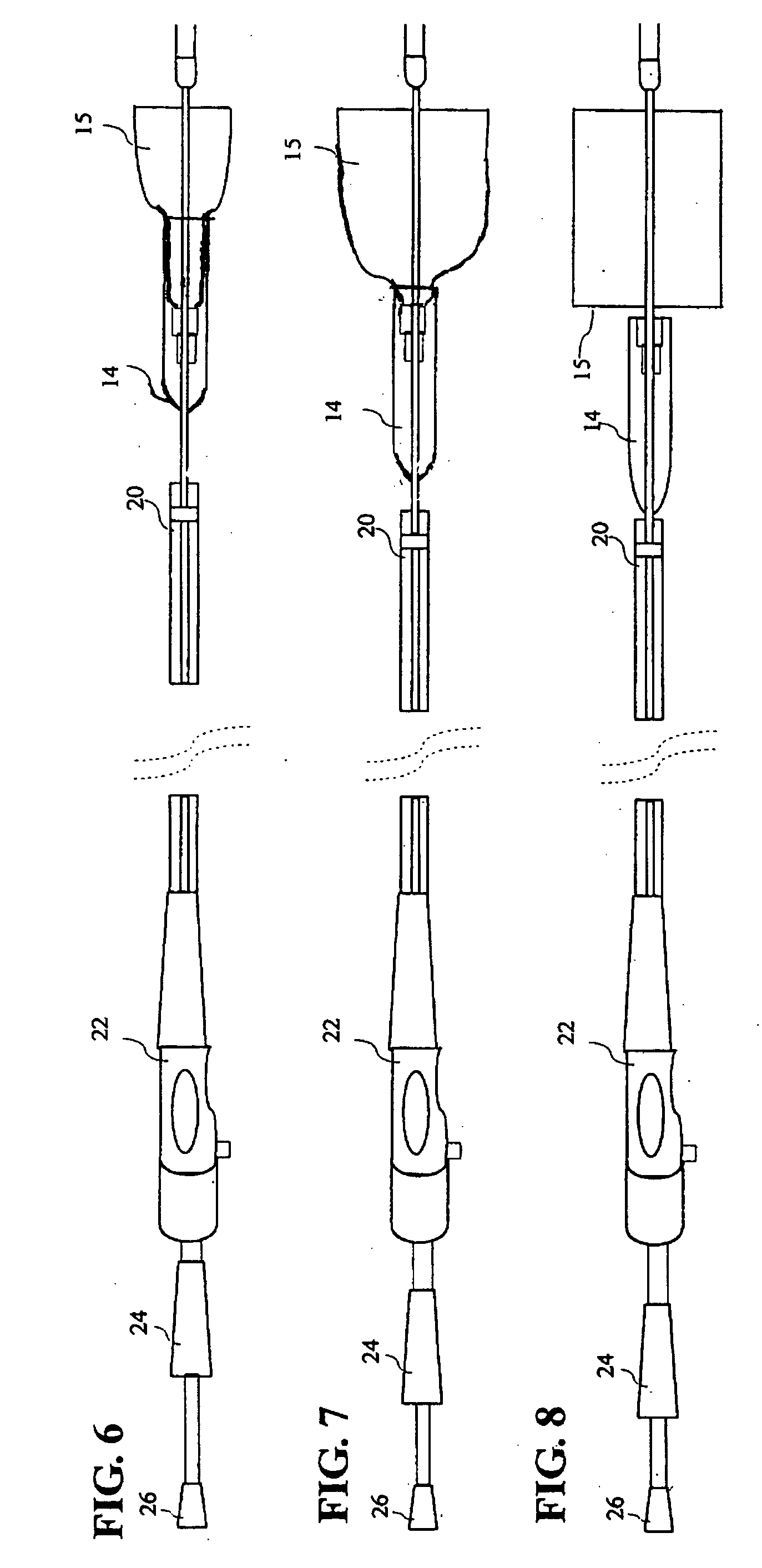
[0009] A stent-graft deployment system, includes a stent-graft and a catheter having a catheter shaft having a tip; a retractable primary sheath and a retractable flexible secondary sheath. In a predeployed condition the flexible secondary sheath contains the stent-graft in a second constrained small diameter configuration around the catheter shaft at a stent graft location of the catheter near the tip and within the retractable primary sheath. When the primary sheath is retracted from around the stent-graft, the flexible secondary sheath containing the stent graft in the second constrained small diameter configuration is exposed and an end portion of the catheter from an end of the tip to a retracted end of the primary sheath has substantially reduced resistance to bending as compared to when the primary sheath is covering the stent graft location of the catheter. Removal of the secondary sheath releases the stent-graft from a radial constraint so that stent-graft deployment occurs as the secondary sheath releases. Removal of the retractable secondary sheath occurs through a secondary sheath retraction handle connected to a proximal end of the retractable flexible secondary sheath, such that retraction of the secondary sheath retraction handle causes a proximal end of the retractable flexible secondary sheath to be pulled along a catheter longitudinal axis toward a proximal end of the catheter. Pulling of the proximal end of the retractable flexible secondary sheath tensions the retractable flexible sheath to retract the sheath along the catheter longitudinal axis to cause progressive deployment of the stent graft from a distal end of the stent graft.

Problems solved by technology

Unfortunately, the semi-rigid sheath may tend to kink in areas having tight radiuses such as the thoracic arch.
Such kinking can increase the deployment force required to place a stent-graft in a target area or even prevent deployment completely.
Unfortunately, these methods introduced a separate non-integrated sheath into the system into the femoral artery and further failed to provide the desired control during deployment.

Method used


Image

  • Double sheath deployment system
  • Double sheath deployment system
  • Double sheath deployment system

Examples


Embodiment Construction

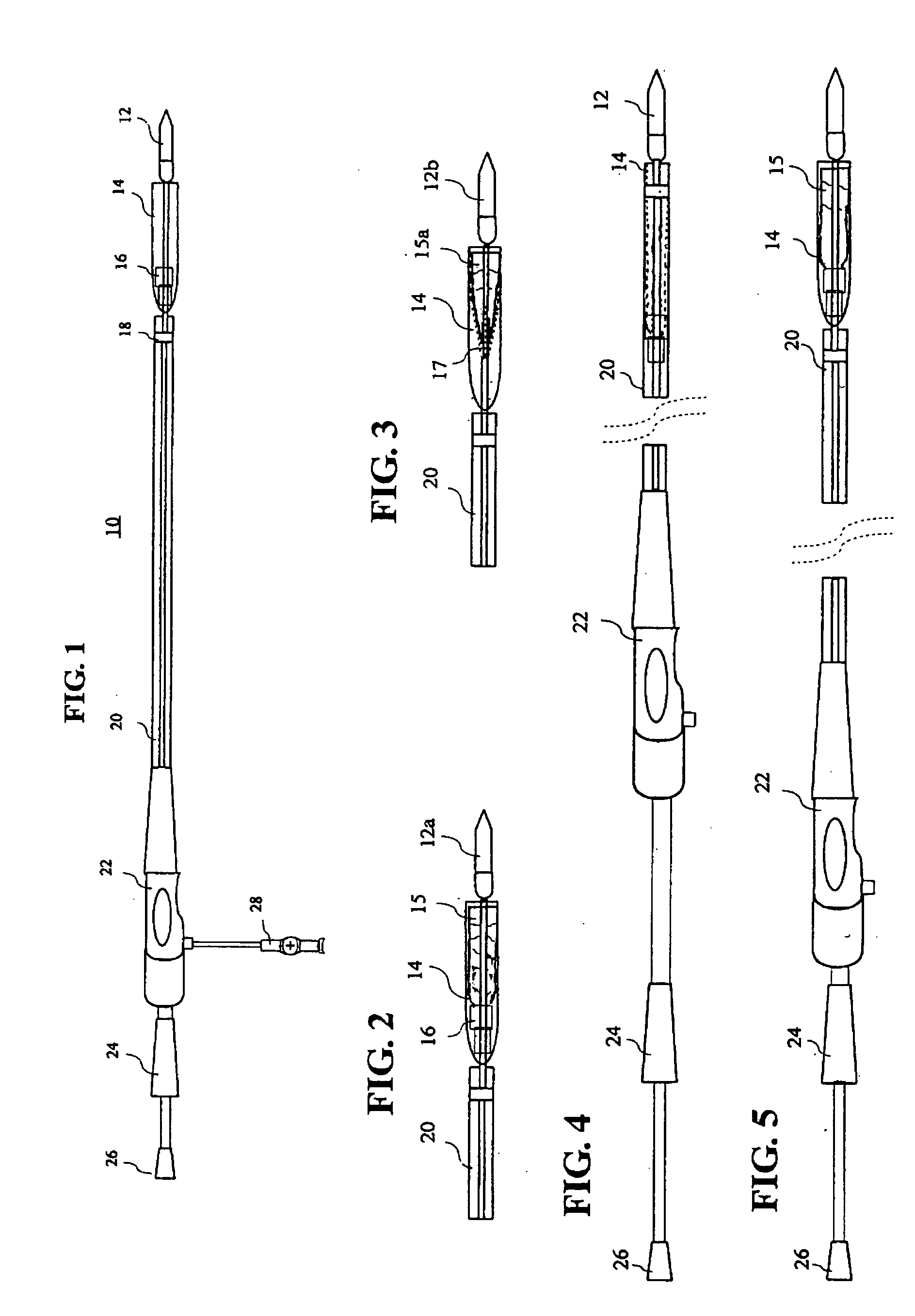
[0026]FIGS. 1-3 show portions of a stent-graft deployment system 10. FIG. 1 illustrates the system 10 without a stent-graft while FIGS. 2 and 3 show close up views of the deployment system tip which are loaded with a stent-graft 15, 15a. This system could also deploy a stent alone or some other form of endoprosthesis. The subsequent use of “stent-graft” herein should be understood to include other forms of endoprosthesis. Ideally, the stent-groft deployment system 10 comprises a tapered tip 12, 12a, 12b that is flexible and able to provide trackability in tight and tortuous vessels, and can bend easily once the primary sheath 20 is retracted. Other tip shapes such as bullet-shaped tips could also be used.

[0027] The system 10 includes a primary sheath 20 (preferably made of a semi-rigid material such as PTFE) initially covering a secondary sheath 14 (preferably made of woven polyethylene terephthalate (PET)). The secondary sheath 14 is more flexible than the retractable primary shea...


PUM


Abstract

A stent-graft deployment system (10) includes a stent-graft (15), a flexible catheter tip (12) attached to a catheter shaft (25), a retractable primary sheath (20) containing the stent-graft in a first constrained small diameter configuration around the catheter shaft near the flexible tip. The stent-graft deployment system further includes a flexible secondary sheath (14) disposed within the retractable primary sheath and also containing the stent-graft, wherein when the primary sheath is removed from around the stent-graft, the flexible secondary sheath contains the stent-graft in a second constrained small diameter configuration around the catheter shaft near the flexible tip. The removal of the secondary sheath releases the stent-graft from a radial constraint so that stent-graft deployment may proceed.

Description

Field Of The Invention [0001] This invention relates generally to medical devices and procedures, and more particularly to a method and system of deploying a stent-graft in a vascular system. BACKGROUND OF THE INVENTION [0002] Prostheses for implantation in blood vessels or other similar organs of the living body are, in general, well known in the medical art. For example, prosthetic vascular grafts formed of biocompatible materials (e.g., Dacron or expanded, porous polytetrafluoroethylene (PTFE) tubing) have been employed to replace or bypass damaged or occluded natural blood vessels. A graft material supported by framework is known as a stent-graft or endoluminal graft. In general, the use of stent-grafts for treatment or isolation of vascular aneurysms and vessel walls which have been thinned or thickened by disease (endoluminal repair or exclusion) are well known. Many stent-grafts, are “self-expanding”, i.e., inserted into the vascular system in a compressed or contracted state...

Claims


Application Information

Patent Timeline
IPC IPC(8): A61F2/06A61F2/84
CPCA61F2002/9517A61F2/95A61F2/9517Y10S623/903
Inventor GREENAN, TREVOR
Owner MEDTRONIC VASCULAR INC
Learn More