

Method and apparatus for manufacturing spark plug
a manufacturing method and spark plug technology, applied in the manufacture of spark plugs, tube/lamp factory adjustment, electric discharge tube/lamps, etc., can solve the problems of deterioration of ignitionability of spark plugs, and achieve the effect of raising the accuracy of the concentric factor and higher precision
- Summary
- Abstract
- Description
- Claims
- Application Information
AI Technical Summary
Benefits of technology
Problems solved by technology
Method used
Image

Examples
first embodiment
(First Embodiment)
In connection with FIGS. 1 to 10, a first embodiment will now be described.
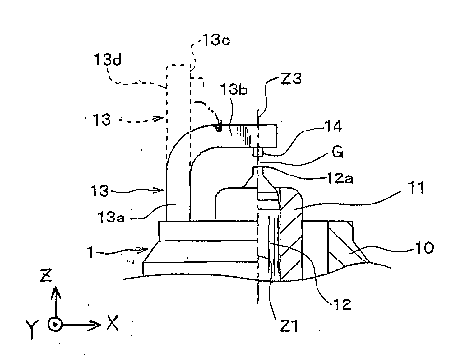
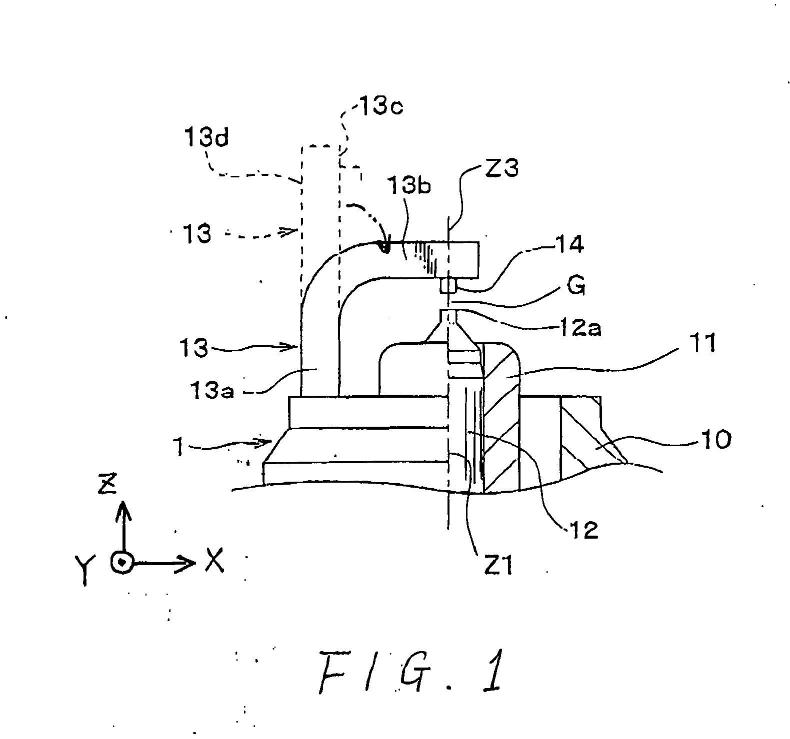
FIG. 1 shows a semi-cross section of the front partial view of a spark plug 1 manufactured based on the manufacturing method according to the present invention. As shown, the spark plug 1 is provided with an approximately cylindrical housing 10 made of a conductive steel material. A substantially cylindrical porcelain insulator 11, made of ceramic, which is highly insulative, is inserted and fixed in the housing 10, with its one end protruding from one end of the housing 11. An axial hole is formed in the porcelain insulator 11.
A center electrode 12 made of a conductive metal material and formed into a substantially cylindrical shape is inserted and fixed in the axial hole of the porcelain insulator 11. A platy earth electrode 13 made of Ni (Nickel)-based alloy is joined on one axial end of the housing 10. On end of the earth electrode 13, there is bonded a columnar noble metal chip 14 m...
second embodiment
(Second Embodiment)
Referring to FIGS. 11-12A and 12B, a second embodiment of the present invention will now be described. For the sake of a simplified explanation, components in the second embodiment which are the same or identical as or to those in the first embodiment are referred with the same reference numerals as those in the first embodiment. This usage of the reference numerals will true of a third embodiment described later.
The manufacturing apparatus and method for spark plugs in the second embodiment have a feature that the bending punch 90 is driven to move obliquely to the center-electrode axial line Z1.
In order to realize such oblique movements of the provisional bending punch 90, the second embodiment uses a provisional bending apparatus AP2 equipped with a divided-structure common block, which corresponds to the common block 101 explained in FIGS. 5 and 6. One of divided blocks is arranged obliquely to the center-electrode axial line Z1 in order to move the provi...
third embodiment
(Third Embodiment)
Referring to FIGS. 13-14, a third embodiment of the present invention will now be described.
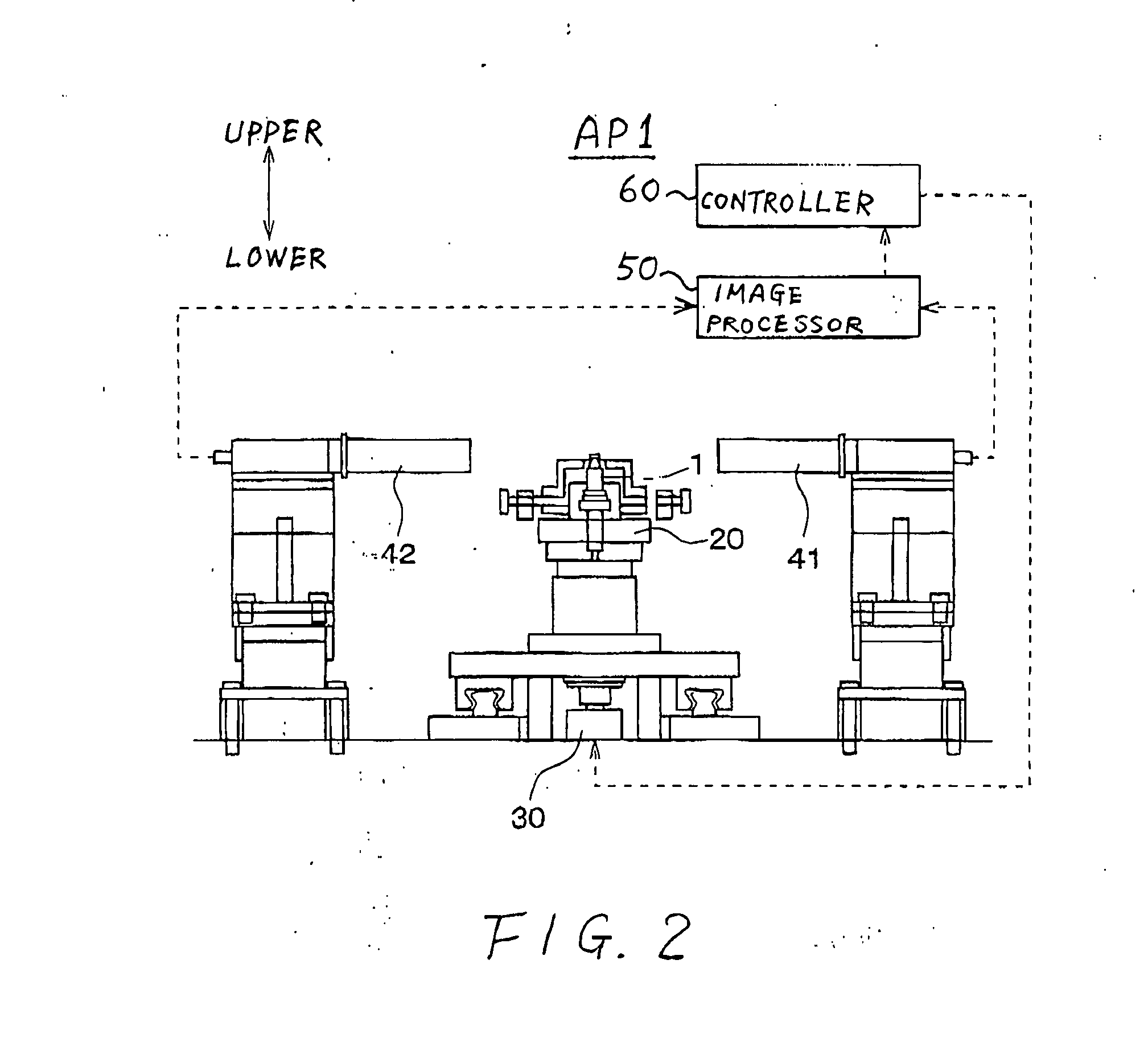
The third embodiment features feedback control of a shift amount S2 between the noble metal chip 14 and the tip 12a of the center electrode 12 in the direction (i.e., the X-axis direction) along which the searchers 81 and 82 are moved during the provisional bending operation, the shift amount S2 being measured after the main bending operation. This second shift amount S2 is obtained through the image processing based on image signals from the cameras 41 and 42.
In the present embodiment, after the main bending process to finely adjust the spark gap between the noble metal chip 14 on the earth electrode 13 and the tip 12a of the center electrode 12 in the center-electrode axial line Z1, the above shift amount S2 is measured (steps S11 and S12 in FIG. 14). Information indicative of this shift amount S2 is fed back to manufacturing the next work (spark plug) (steps S13 and ...
PUM
| Property | Measurement | Unit |
|---|---|---|
| Angle | aaaaa | aaaaa |
| Dimension | aaaaa | aaaaa |
| Height | aaaaa | aaaaa |
Abstract
Description
Claims
Application Information