
A/C - D/C power system with internal fuel cell

a fuel cell and power system technology, applied in secondary cell servicing/maintenance, emergency power supply arrangements, instruments, etc., can solve problems such as inconvenience to a life-threatening deficiency, time element required, and loss of mobile telephone calls

Inactive Publication Date: 2005-02-24
MTI MICROFUEL CELLS
View PDF17 Cites 50 Cited by
  • Summary
  • Abstract
  • Description
  • Claims
  • Application Information

AI Technical Summary

Benefits of technology

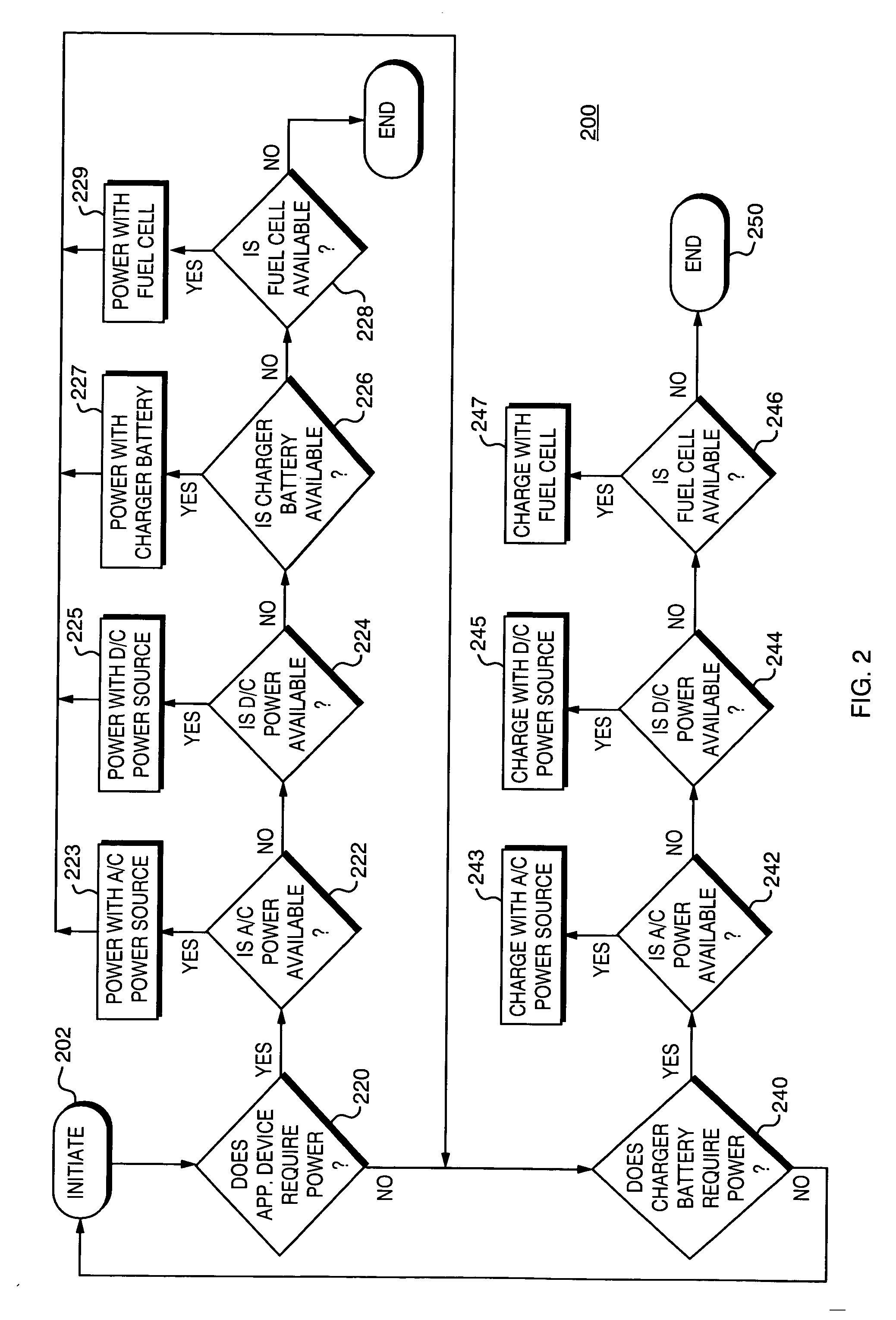
[0014] The disadvantages of prior techniques are overcome by solutions provided by the present invention, which is an A/C-D/C power system including an internal, independently powered fuel cell (herein referred to as an “A/C-D/C-F/C system”). The system includes a portable power unit that can accept electrical current from an alternating current (“A/C”) source—typically from a standard electrical outlet; and a direct current (“D/C”) source—perhaps from an automobile lighter unit, though other D/C sources may be available. In addition the device also includes a direct oxidation fuel c...

Problems solved by technology

This creates problems where the application device user is in traffic, or otherwise does not have access to another source of electricity.
The opportunity to make a mobile telephone call, or to send Email messages, or use a PDA, for example, has been lost.
The problem may be anything from a mere inconvenience to a life-threatening deficiency, depending on the particular circumstances in which the user finds themselves.
Furthermore, even though many application devices include rechargeable batteries, there is a time element required for a recharge, particularly a full recharge, of the application device batteries.
Thus, even though an external power source may be available to recharge a battery, it may not be convenient or possible for the user to tether the device to that external power source at that time.
Thus, these devices must be kept sealed while not in use, and even then, air leakage into the cartridge can still cause a small, but continual discharge diminishing their effectiveness over time.
Thus, the cell does not continue to provide electricity unless fuel is introduced into the anode chamber.

Method used


Image

  • A/C - D/C power system with internal fuel cell
  • A/C - D/C power system with internal fuel cell
  • A/C - D/C power system with internal fuel cell

Examples


embodiment

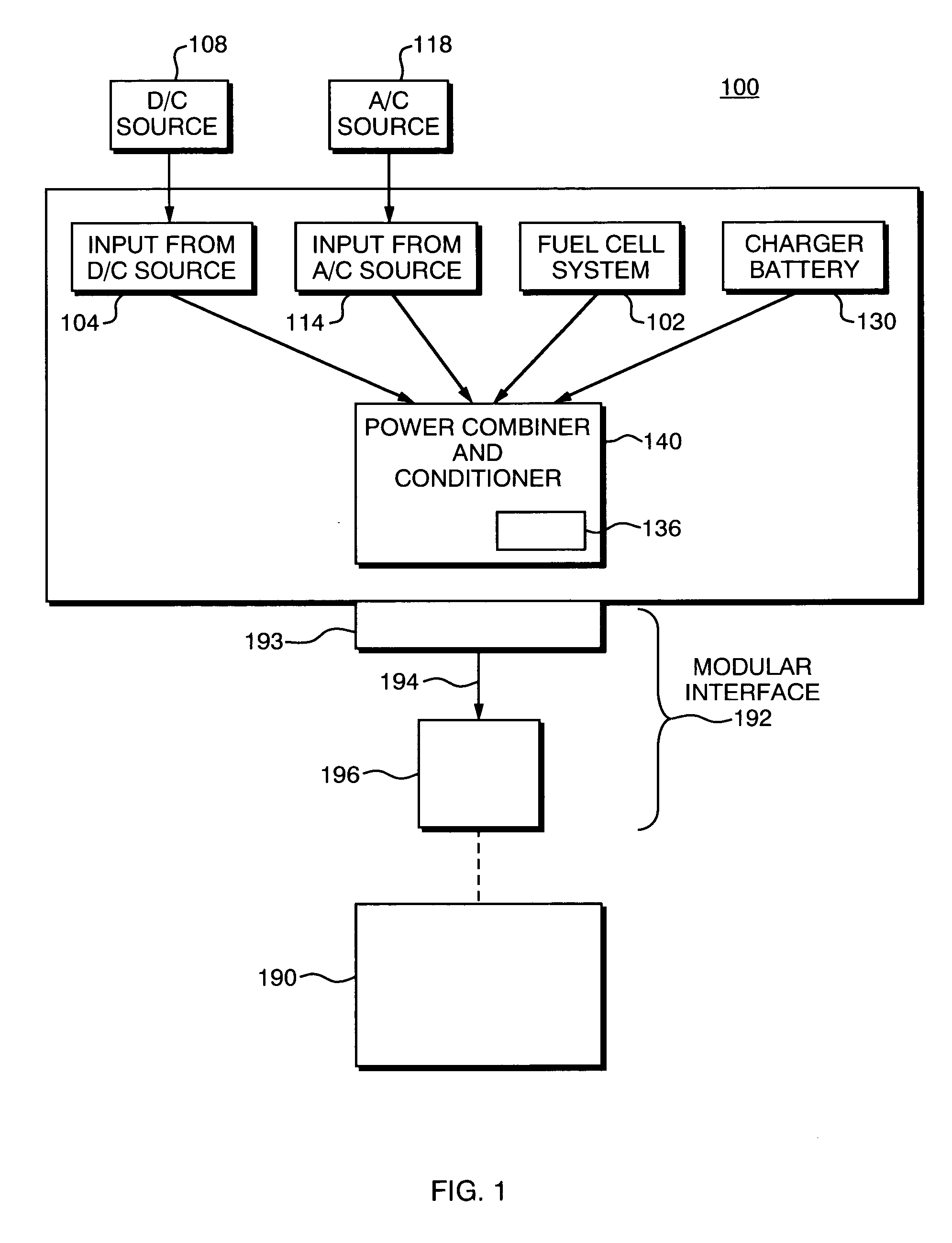
[0022]FIG. 1 illustrates an A / C-D / C-F / C unit 100 that includes a direct oxidation fuel cell system 102, which is preferably a direct methanol fuel cell. The A / C-D / C-F / C unit 100 is preferably a portable unit that can be conveniently carried about, though more stationary units also fall within the scope of the invention. The A / C-D / C-F / C unit 100 has as inputs a D / C source input 104 by which the unit 100 may be connected to a direct current source, typically an automobile lighter, as is illustrated in schematic form as block 108 in FIG. 1. The unit 100 also includes an A / C source input 114, by which the unit 100 may be connected to an alternating current source, typically a standard electrical outlet. The A / C input 114 and D / C input electrically connects the unit 100 to an external alternating current source 118 or external direct current source 108, respectively. A / C input 114 and D / C input 104 may be simple electrical connectors.

[0023] Power combiner and conditioner 140 receives th...


PUM


Abstract

An A / C-D / C-F / C power system is provided that includes a portable power unit that can accept electricity from a number of alternative sources including an AC power source, a DC power source, a battery, and a direct oxidation fuel cell. In accordance with one embodiment of the invention, the fuel cell is used to either recharge a battery, or to power an application device, when the AC source and / or the DC source are unavailable. The A / C-D / C-F / C system of the present invention also includes signal processing and signal conditioning circuitry in a power combiner and conditioner, which condition the voltage signal to deliver power to the application device in a manner that is consistent with device requirements.

Description

CROSS-REFERENCE TO RELATED APPLICATION [0001] The present application claims the benefit of U.S. Provisional Patent Application Ser. No. 60 / 415,061, which was filed on Oct. 1, 2002, by Judith A. Barnes et al. for an A / C-D / C POWER SYSTEM WITH INTERNAL FUEL CELL and is hereby incorporated by reference.BACKGROUND OF THE INVENTION [0002] 1. Field of the Invention [0003] This invention relates generally to battery powered electronic devices, and more particularly, to systems for recharging and maintaining operation of such battery powered electronic devices. [0004] 2. Background Information There are a multitude of battery powered devices which are in wide-spread use today including laptop computers, cell phones, personal digital assistants (PDAs), walkie-talkies, cordless power tools, and mobile video and video game systems. These devices typically operate using a battery that is recharged when the device is not in use. Often, the battery is recharged by connecting either the device (or...

Claims


Application Information

Patent Timeline
IPC IPC(8): G06F1/26H01M16/00H02J7/00H02J7/32H02J7/34H02J9/06
CPCG06F1/263H01M16/006Y02B90/14H02J7/34H02J9/061H02J7/0055H02J2207/40Y02B90/10Y02E60/10Y02E60/50
Inventor BARNES, JUDITH A.BUNCH, JAMES T. JR.
Owner MTI MICROFUEL CELLS
Learn More