Optically encoded particles

a technology of optically encoded particles and particles, applied in the field of encoding, can solve the problems of slow diffusion rate of labeling/encoding itself, difficult to obtain number, and limit the concentration range of analytes being sensed in positional arrays

Active Publication Date: 2005-02-24
RGT UNIV OF CALIFORNIA
View PDF89 Cites 134 Cited by
  • Summary
  • Abstract
  • Description
  • Claims
  • Application Information

AI Technical Summary

Problems solved by technology

At the microscale, however, labeling / encoding itself becomes difficult.
Positional arrays, however, can suffer from slow diffusion rates and limits on the concentration ranges of analytes being sensed.
In practice, this number is difficult to obtain because of spectral overlap and sample inhomogeneities.
Also, despite the increased photostability of quantum dots, fluorescence quenching is still possible, casting uncertainty on using relative intensity measurements as a reliable encoding method.
Deposition of rods is a relatively complex process, however, and maybe difficult to apply as an encoding strategy where, for example, a large number of codes is desirable because each rod must be brought into focus in an optical reader (such as a microscope) in order to read out the codes.

Method used


Image

  • Optically encoded particles
  • Optically encoded particles
  • Optically encoded particles

Examples


example embodiments

and Experimental Data

[0032] Example embodiments of the invention will now be discussed. Experimental data is included for the purpose of illustrating to artisans the potential of the invention. Where given, equipment is specified only to allow artisans to understand experimental data reported herein. Commercial embodiment devices of the invention may take substantially different form, permitting low cost mass manufacturing, for example.

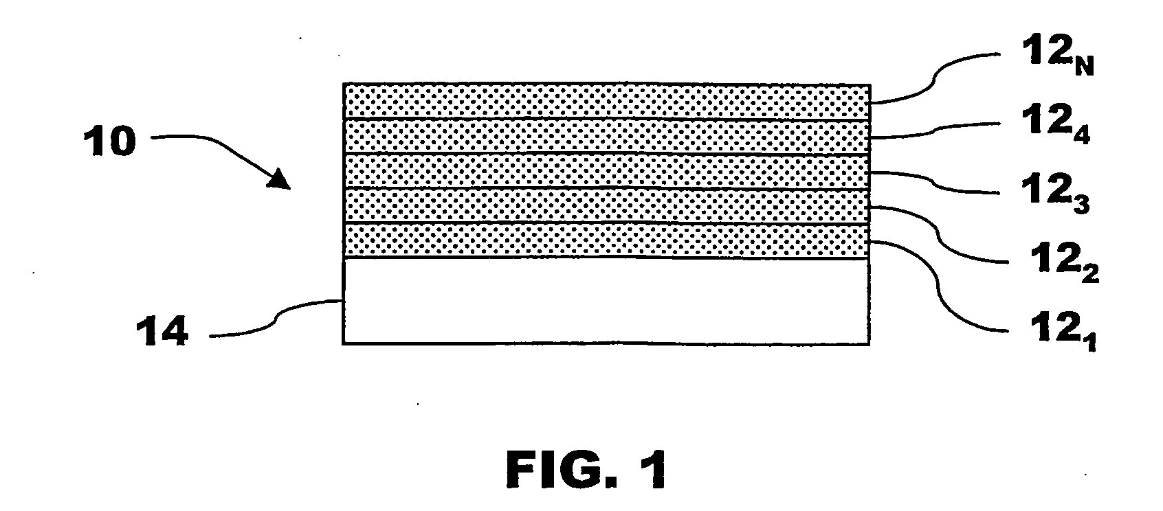
[0033] A first example embodiment is stand-off detection. This is a chemical detection technique to identify an analyte from a distance. A particle 10 of the invention includes a receptor to sense a particular analyte. Both the code of the particle and an indication of binding of the analyte can be detected in the reflectivity spectrum, for example, with use of a low power laser. The receptor, for example, can be specific to sense biomolecules or to attach the encoded particle to a cell, spore, or pollen particle.

[0034] A test of stand-off detection...


PUM

PropertyMeasurementUnit
refractive indexaaaaaaaaaa
current densityaaaaaaaaaa

Abstract

The invention concerns a particle having a code embedded in its physical structure by refractive index changes between different regions of the particle. In preferred embodiments, a thin film possesses porosity that varies in a manner to produce a code detectable in the reflectivity spectrum.

Description

TECHNICAL FIELD [0001] A field of the invention is encoding. Additional exemplary fields of the invention include the life sciences, security, product marking, food processing, agriculture, and chemical detection. BACKGROUND ART [0002] A well-appreciated need for labeling exists in society. Labeling is a fundamental basis for tracking and identifying. Encoding can be used as a form of labeling understood by persons or equipment, as in the case of bar coding. At the microscale, however, labeling / encoding itself becomes difficult. [0003] Strategies to encode microscale materials have accordingly received increased attention for such uses as high-throughput screening in the fields of drug discovery, genetics screening, biomedical research, and biological and chemical sensing. Concurrent research strategies for measuring an increased number of analytes while minimizing the necessary sample volume have focused on either on-chip spatially differentiated arrays or encoded beads. Large arra...

Claims


Application Information

Patent Timeline
Patent Type & Authority Applications(United States)
IPC IPC(8): G01N21/00G01N21/31G01N21/45G09F3/00
CPCG01N21/31G01N21/45G09F3/00B05D1/00Y10T436/13G06K19/06084G06K19/0614Y10T436/144444Y10T436/143333B05D2451/00
Inventor SAILOR, MICHAEL JSCHMEDAKE, THOMAS
Owner RGT UNIV OF CALIFORNIA
Why Eureka
Try Eureka