Automatic/manual longitudinal position translator and rotary drive system for catheters

a translation system and translational technology, applied in the field of catheter systems, can solve the problems of limited blood flow, serious risk to the health of people, and constant translational rate of the device, and achieve the effect of facilitating the distally pushing of the cabl

Inactive Publication Date: 2005-02-24
BOSTON SCI SCIMED INC
View PDF28 Cites 46 Cited by
  • Summary
  • Abstract
  • Description
  • Claims
  • Application Information

AI Technical Summary

Benefits of technology

[0016] Another advantage of the invention results when the connection between the first and second combined connectors is a blind matable connection. That is, the connectors need only be properly aligned so pushing the two connectors together causes them to properly mate. Preferably, the data / information connection is made using coaxial plug and socket connectors which not only provide the desired electrical, optical or other type of connection, but also provides sufficient frictional engagement between the first and second combined connectors to permit the longitudinal movement of the elongate operative element (e.g. cable) within the sheath. While the frictional engagement between the two data / information connectors may be enough to provide an acceptable rotary drive interface, it is preferred that the first and second combined connectors include first and second rotary drive connectors including rotary drive surfaces. These rotary drive surfaces are preferably arranged to guide the two connectors into proper rotary alignment when engaged.
[0017] The proximal portion of the cable is preferably much stiffer than the remainder of the cable. This helps to ensure a fluid-tight seal can be provided between the cable and the proximal portion of the sheath. This is important when a fluid or flush port is provided distally of such seal; the seal helps to prevent the fluid from entering into the drive assembly. In addition, this stiff, proximal portion can be made sufficiently long so that when the rotary driver is in the longitudinally pulled-back or proximal position, only the stiff proximal portion of the cable is exterior of the sheath and inside the drive assembly. The stiff portion of the cable is stiff enough to be self-supporting and does not droop within the drive assembly. Pushing the cable distally is also facilitated by the use of a cable with a stiff proximal portion.

Problems solved by technology

Blood flow is restricted and the person's health is at serious risk.
Two major difficulties in using such devices are maintaining a constant translational rate for the device and obtaining images of and information on the region of the blood vessel to be treated.
Even with the most skilled physician, it is practically impossible to manually exercise sufficiently slow constant rate longitudinal translation of the ultrasound imaging device (which thereby provides for a precisely known separation distance between adjacent data samples).
This division of the physician's attention and difficulty in providing a sufficiently slow constant translation rate can result in some diagnostic information being missed.
Similarly, it is difficult for physicians to manually control the translational rate of atherectomy catheters and other interventional devices that are longitudinally advanced and retracted through blood vessel and other body lumens.
While such a longitudinal translation assembly can work well, it is relatively large, bulky and heavy; it is expensive; and it is cumbersome to set up, in part because the rotary drive and longitudinal translation assemblies are wrapped in separate sterile drapes (plastic bags) for sterility.
One drawback with conventional catheter imaging systems is the cost of replacing the disposable catheter assembly.
These electronic components are disposed of with the rest of the catheter assembly which raises the cost of the procedure.

Method used


Image

  • Automatic/manual longitudinal position translator and rotary drive system for catheters
  • Automatic/manual longitudinal position translator and rotary drive system for catheters
  • Automatic/manual longitudinal position translator and rotary drive system for catheters

Examples


Embodiment Construction

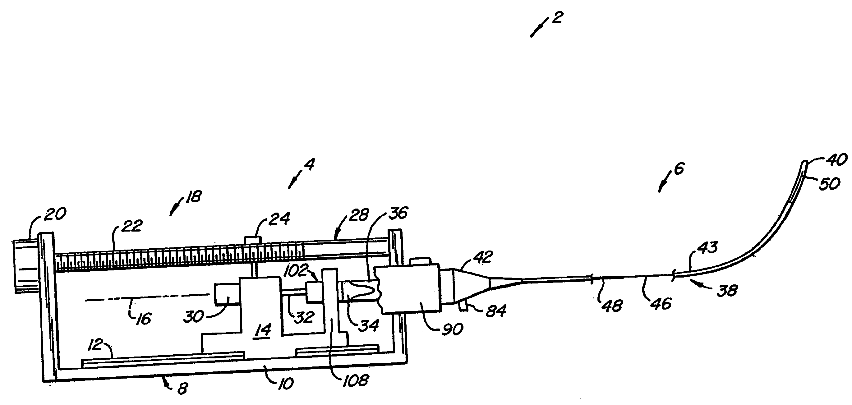
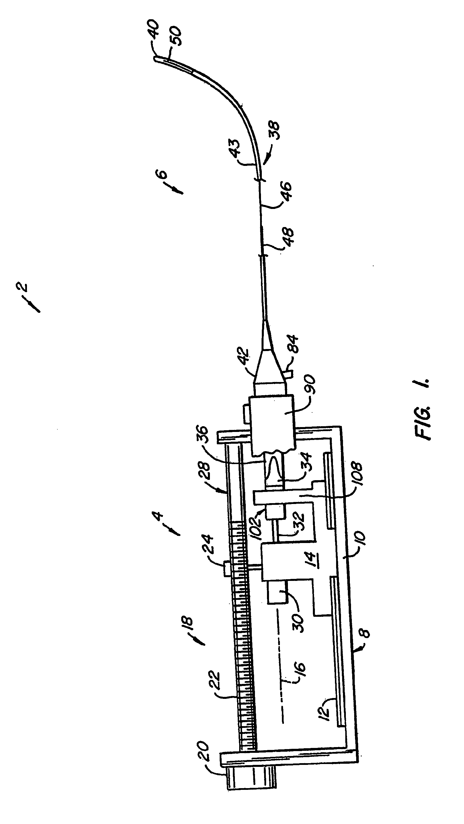
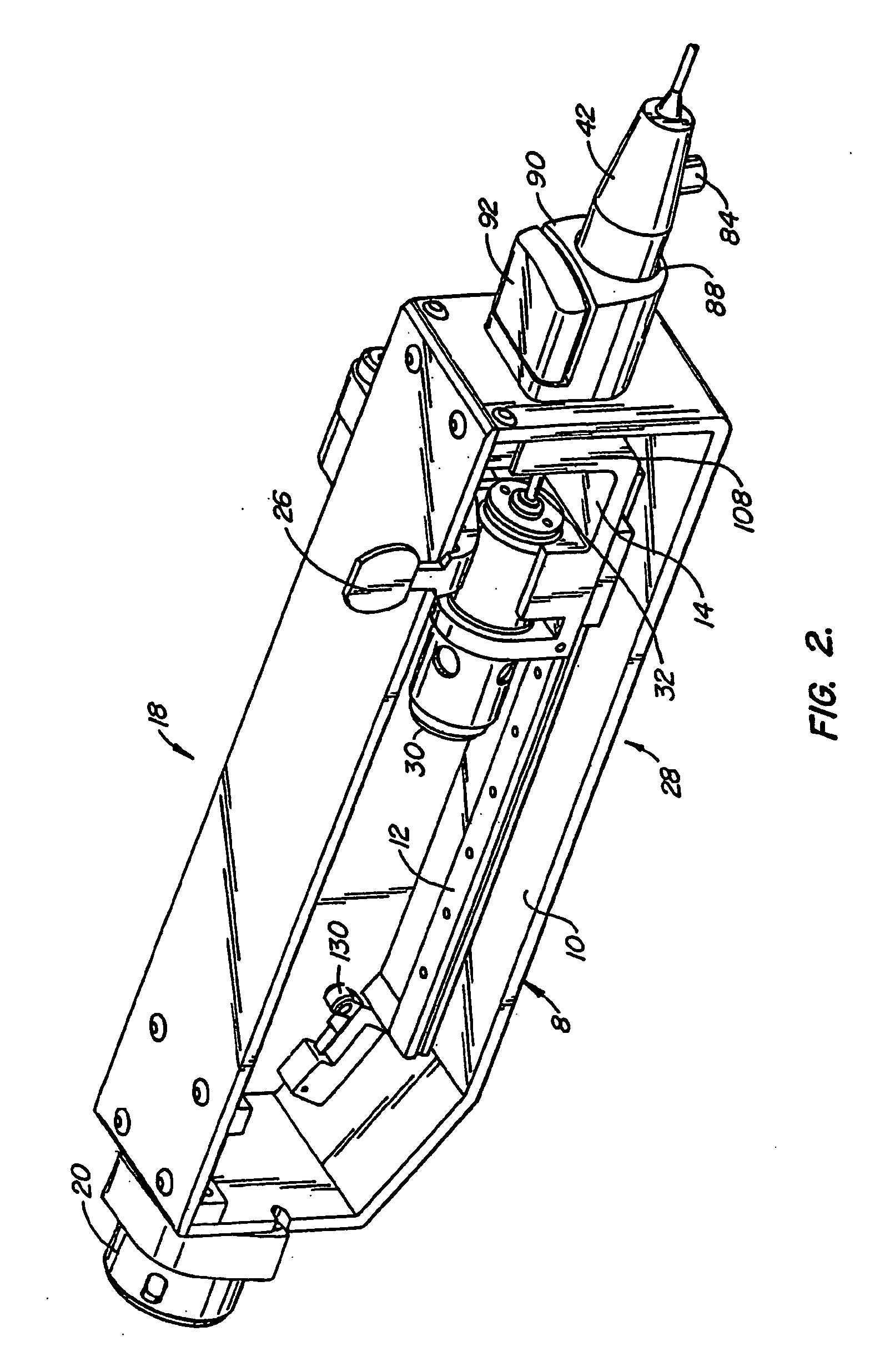
[0028]FIG. 1 illustrates, in schematic form, a catheter system 2 including a drive assembly 4 to which a typically disposable catheter assembly 6 is removably mounted. Referring now also to FIGS. 2 and 2A, drive assembly 4 includes a body 8 having a base 10 supporting a linear bearing track 12. A drive chassis 14 is mounted for linear movement along a longitudinal path 16 by a longitudinal driver 18. Longitudinal driver 18 includes a longitudinal drive motor 20 which rotates a longitudinal drive screw 22 rotatably supported at each end by body 8. Driver 18 also includes a threaded clamp 24 having threads-which match the threads on drive screw 22. Clamp 24 is mounted to and moves with drive chassis 14. Clamp 24 is normally biased into engagement with drive screw 22, but can be moved out of engagement with drive shaft 22 by the user moving a drive clamp handle 26; doing so disengages clamp 24 from drive screw 22 and permits the user to move drive chassis 14 along longitudinal path 16....


PUM


Abstract

An automatic pullback catheter system (2) includes a disposable catheter assembly (6) mountable to a drive assembly (4). The drive assembly includes a body (8) to which a drive. chassis (14) is mounted for movement along a longitudinal path (16) by a motor (20) which rotates a longitudinal drive screw (22) selectively coupled to the drive chassis by a threaded clamp (24). A rotary drive motor (30), mounted to the drive chassis, rotates a first combined connector (34). The catheter assembly includes a hollow sheath (38) housing a rotatable and axially movable cable assembly (44). The sheath includes a proximal hub (42) mountable to the body. The cable assembly includes an elongate imaging cable (46) with a second combined connector (36) at its proximal end. The first and second combined connectors are blind matable connectors and provide for the longitudinal movement coupling, the rotary movement coupling and the data / information connection of the two connectors.

Description

CROSS-REFERENCE TO RELATED APPLICATIONS [0001] This is related to U.S. patent application Ser. No. 09 / 047,064, filed May 7, 1998 and entitled “Combined Motor Drive and Automatic Longitudinal Position Translator for Ultrasonic Imaging System”; U.S. patent application Ser. No. 08 / 721,433 filed Sep. 27, 1996 and entitled “Catheter System and Drive Assembly Thereof”; U.S. patent application Ser. No. 08 / 722,325 filed Sep. 27, 1996 and entitled “Device for Controlled Longitudinal Movement of an Operative Element Within a Catheter Sheath and Method”; and U.S. Pat. No. 5,361,768, issued Nov. 8, 1994 and entitled “Automated Longitudinal Position Translator for Ultrasonic Positioning Probes, and Method of Using Same”.BACKGROUND OF THE INVENTION [0002] The present invention relates generally to catheters systems. In particular, the present invention is directed to a catheter system that provides for the controlled longitudinal movement of an elongate element—such as a rotatable imaging core wi...

Claims


Application Information

Patent Timeline
Patent Type & Authority Applications(United States)
IPC IPC(8): A61M25/02A61B8/12A61M25/01A61M25/08A61M25/18A61M39/00
CPCA61B8/4461A61B8/12
Inventor MANSOURI-RUIZ, IDRISS
Owner BOSTON SCI SCIMED INC
Why Eureka
Try Eureka