Robotic apparatus

Active Publication Date: 2005-02-24
MASSACHUSETTS INST OF TECH
View PDF29 Cites 241 Cited by
  • Summary
  • Abstract
  • Description
  • Claims
  • Application Information

AI Technical Summary

Benefits of technology

A final preferred embodiment of the invention is a method of controlling such a manipulator, when the slave unit linkage is characterized by a number X of DOFs, X being at least seven DOFs and the master unit linkage is characterized by a number Y of DOFs where Y is at least one fewer than X, the method further comprising the

Problems solved by technology

However, only about 1,000,000 of the surgeries currently use these techniques, due to limitations in minimally invasive surgical instruments and techniques and the additional training required to master them.
There are many disadvantages of current minimally invasive surgical technology.
The surgeon is deprived of three-dimensional depth cues and may have difficulty correlating hand movements with the motions of the tools displayed on the video image.
Second, the instruments pivot at the point where they penetrate the body wall, causing the tip of the instrument to move in the opposite direction to the surgeon's hand.
Third, existing MIS instruments deny the surgeon the flexibility of tool placement found in open surgery.
Those that include any articulation have only limited maneuverability.
Fourth, the length and construction of many endoscopic instruments reduces the surgeon's ability to feel forces exerted by tissues and organs on the end effector of the tool.
However, despite surgeons' adaptation to the limitations of endoscopic surgery, the technique has brought with it an increase in some complications seldom seen in open surgery, such as bowel perforations due to tr

Method used


Image

  • Robotic apparatus
  • Robotic apparatus
  • Robotic apparatus

Examples


Example

MECHANISM OVERVIEW

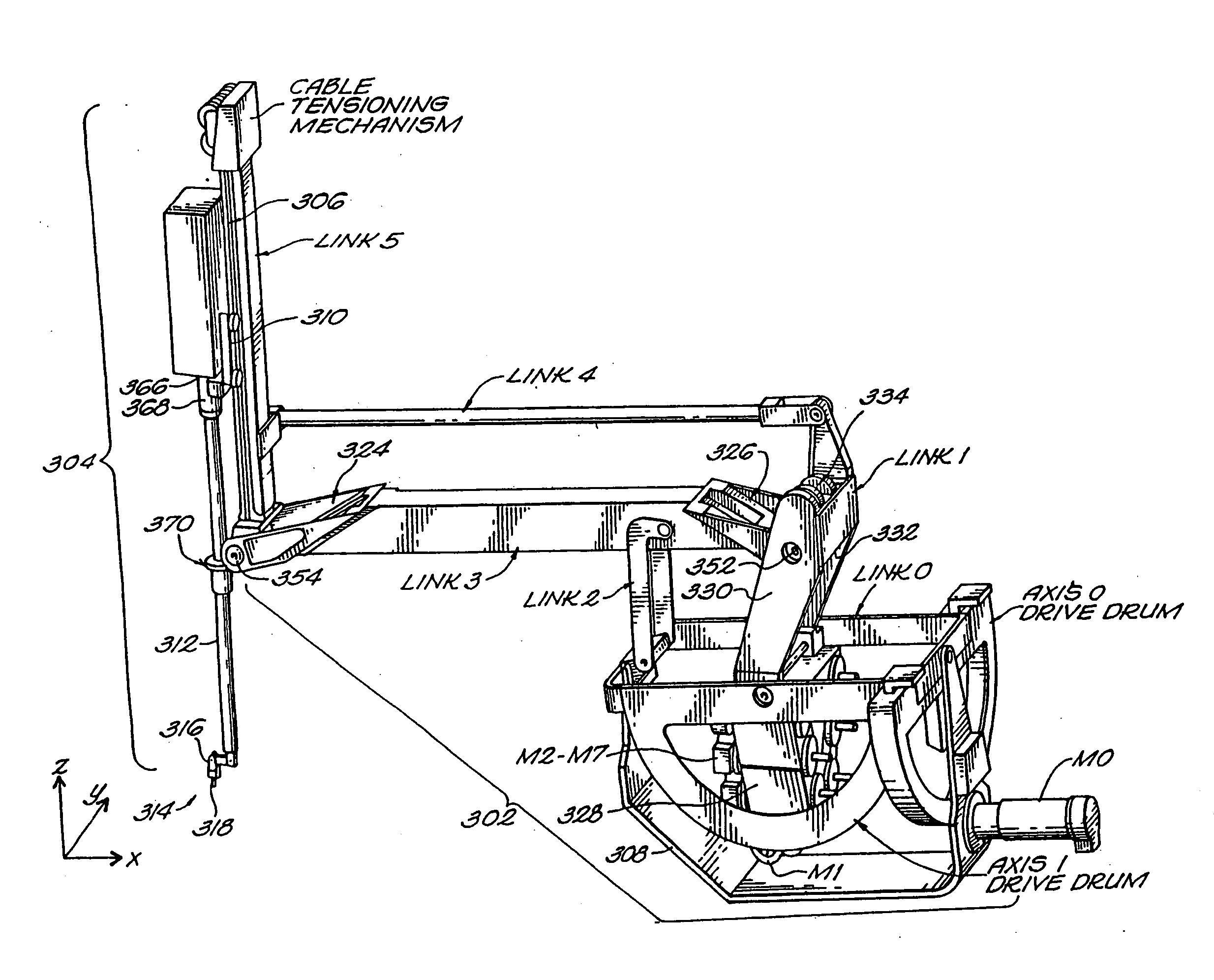
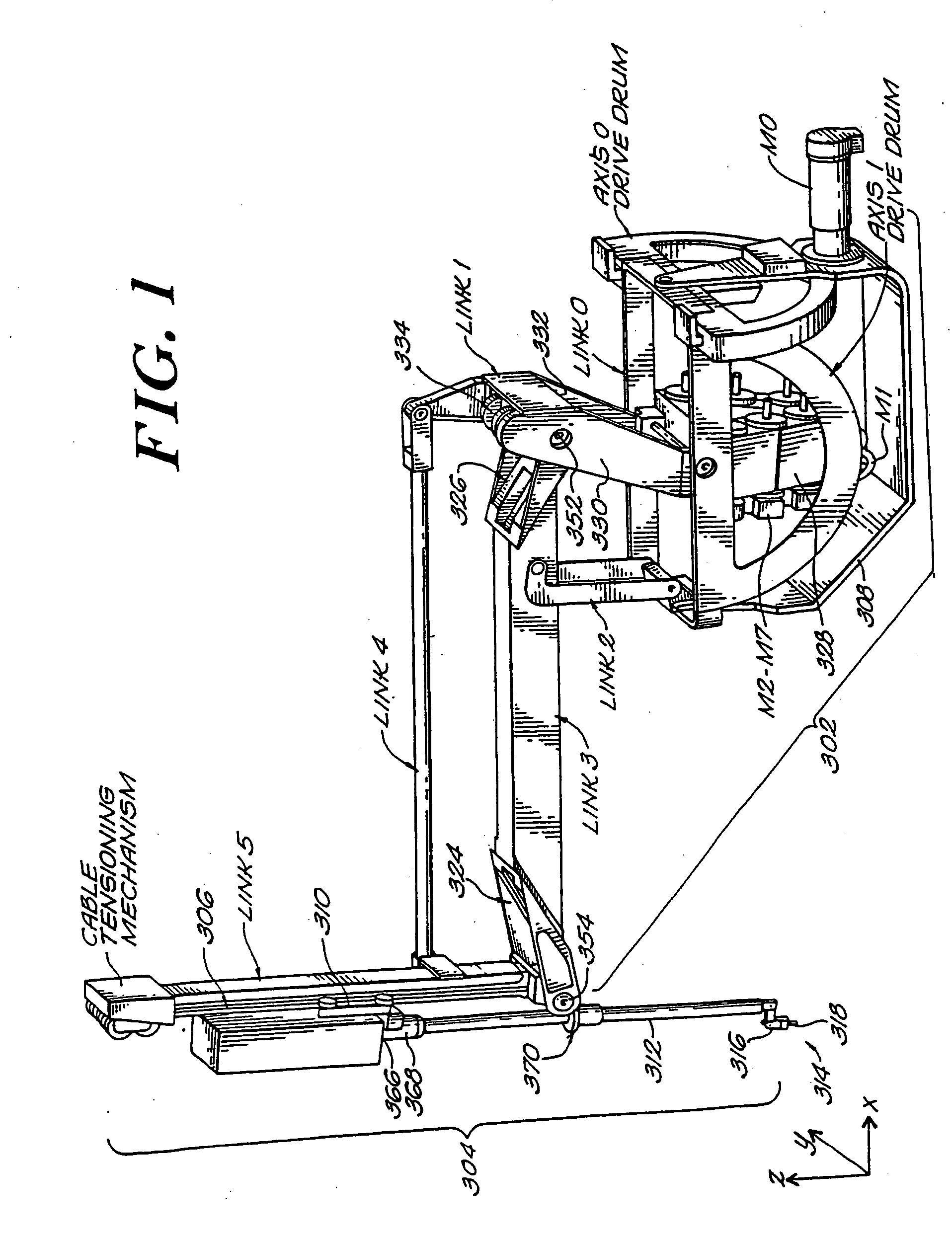
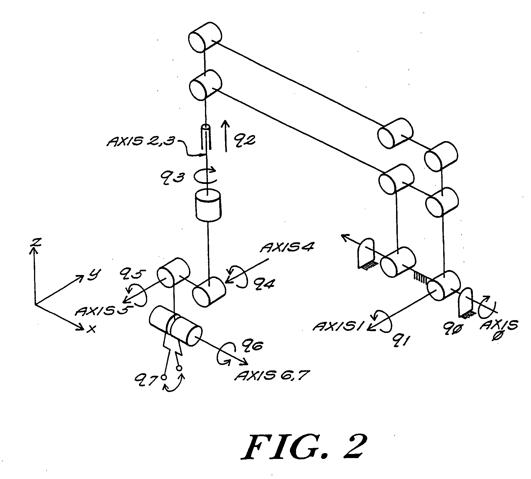
The following is an overview of the system. More details are provided in subsequent sections. A preferred embodiment of a slave apparatus of the invention is shown in FIG. 1 and consists of two main subsystems, a base unit 302 and a wrist unit 304. The base unit contains all of the actuators M0-M7 for the entire system, the links link 0-link 5 and provides a mechanical interconnect 306 for the wrist unit 304, which wrist is a passive (i.e. contains no actuators) detachable instrument. The following components are referred to in FIG. 1, and the kinematic structure, including axis and link numbers, is defined in the schematic drawing FIG. 2. Eight joints are labeled 0-7. (The links are not necessarily associated with respectively numbered axes.) The system is grounded through a ‘U”-shaped stationary base bracket' 308. A spindle link 0, rotates within this base about axis 0. Motor M0 actuates this axis 0 using a cable drive connected to the axis 0 drive drum. Link 1...


PUM


Abstract

A robotic apparatus has eight actuators (M0-M7) and a linkage (LINK 0-LINK 5) that actuates an end effector. Three serial macro freedoms have large ranges of motion and inertias. Four serial micro freedoms have small ranges of motion and inertias. Translation of the end effector in an y direction is actuated by at least one micro joint and at least one macro joint. The apparatus can be part of a master and slave combination, providing force feedback without any explicit force sensors. The slave is controlled with an Inverse Jacobian controller, and the mater with a Jacobian Transpose controller. A slave having more degrees of freedom (DOFs) than the master can be controlled. A removable effector unit actuates its DOFs with cables. Beating heart surgery can be accomplished by commanding the slave to move with a beating heart and cancelling out any such motion in the motions perceived by the master.

Description

BACKGROUND OF THE INVENTION Minimally invasive surgery (“MIS”) techniques reduce the amount of extraneous tissue that are damaged during diagnostic or surgical procedures, thereby reducing patient recovery time, discomfort, and deleterious side effects. It is estimated that 7,000,000 surgeries performed each year in the United States can be performed in a minimally invasive manner. However, only about 1,000,000 of the surgeries currently use these techniques, due to limitations in minimally invasive surgical instruments and techniques and the additional training required to master them. Advances in minimally invasive surgical technology could have a dramatic impact. The average length of a hospital stay for a standard surgery is 8 days, while the average length for the equivalent minimally invasive surgery is 4 days. Thus the complete adoption of minimally invasive techniques could save 24,000,000 hospital days, and billions of dollars annually in hospital residency costs alone. P...

Claims


Application Information

Patent Timeline
IPC IPC(8): A61B19/00B25J3/00B25J9/16
CPCA61B19/22Y10S901/29A61B2017/00703A61B2019/2223A61B2019/223A61B2019/2234A61B2019/2242A61B2019/2246A61B2019/2292A61B2019/2296A61B2019/265B25J3/00B25J9/1615A61B2017/00477A61B19/2203A61B2034/715A61B2090/506A61B34/71A61B34/30A61B34/37A61B34/35A61B2034/305A61B34/77A61B34/70A61B34/76A61B2034/306A61B90/98A61B2034/2057A61B2034/2065Y10S901/10A61B2017/00075A61B2017/00212B25J9/1689B25J9/1697B25J19/021
Inventor MADHANI, AKHIL JITENSALISBURY, J. KENNETHNIEMEYER, GUNTER D.
Owner MASSACHUSETTS INST OF TECH
Why Eureka
Try Eureka