
Drying apparatus

Active Publication Date: 2005-03-03
QINGDAO HAIER WASHING MASCH CO LTD +1
View PDF4 Cites 70 Cited by
  • Summary
  • Abstract
  • Description
  • Claims
  • Application Information

AI Technical Summary

Benefits of technology

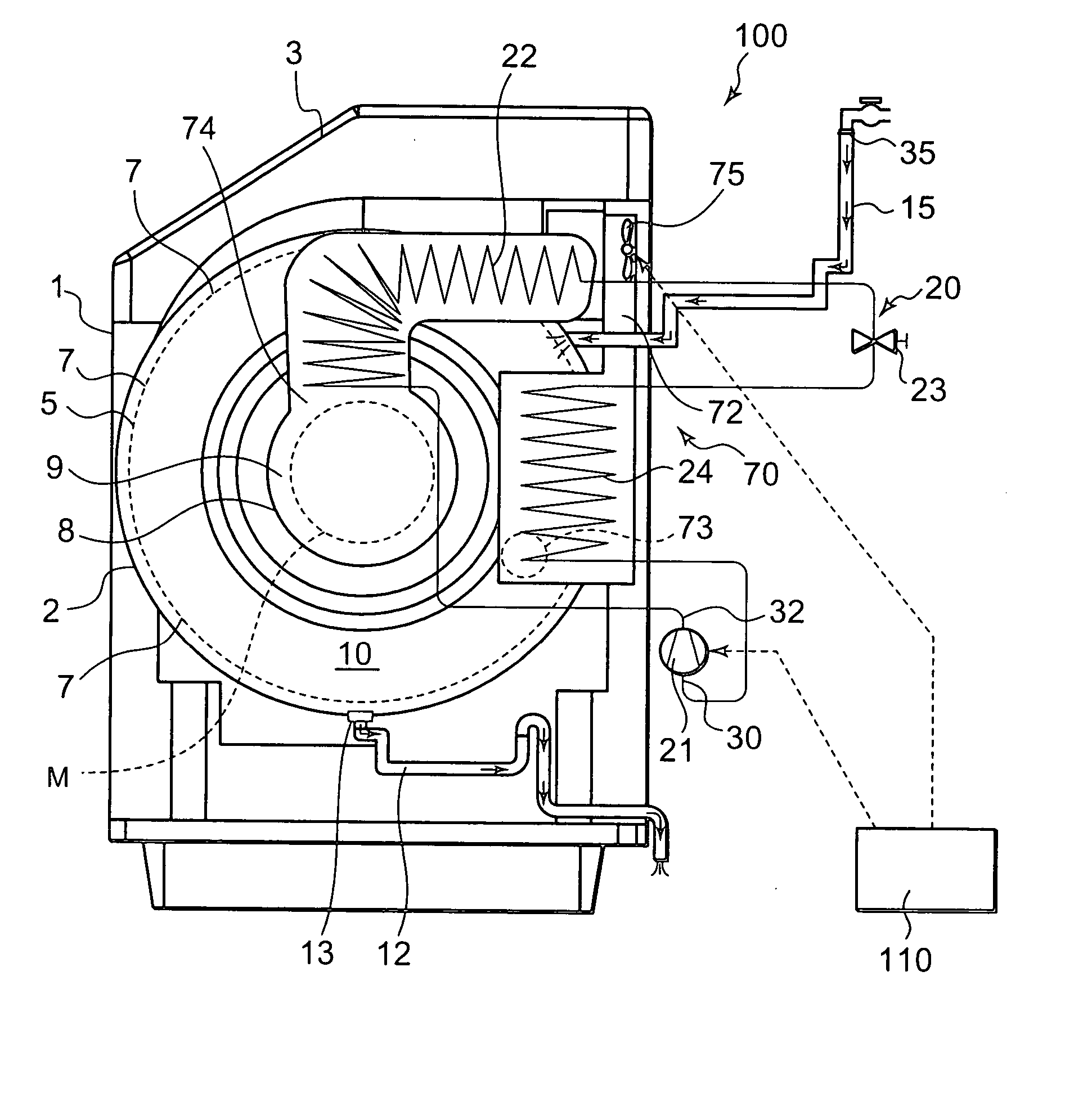
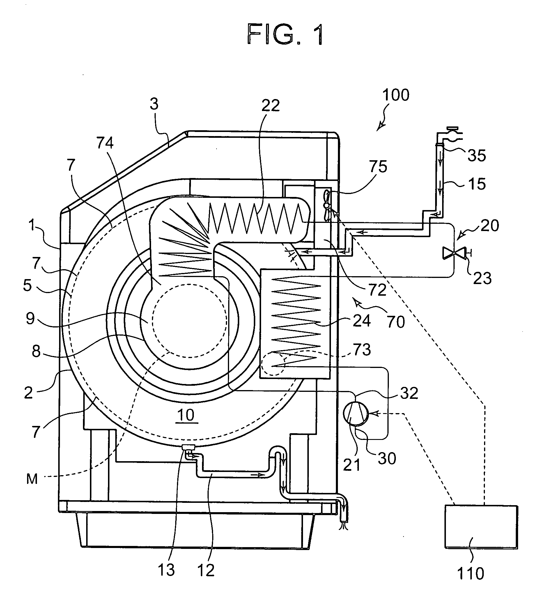
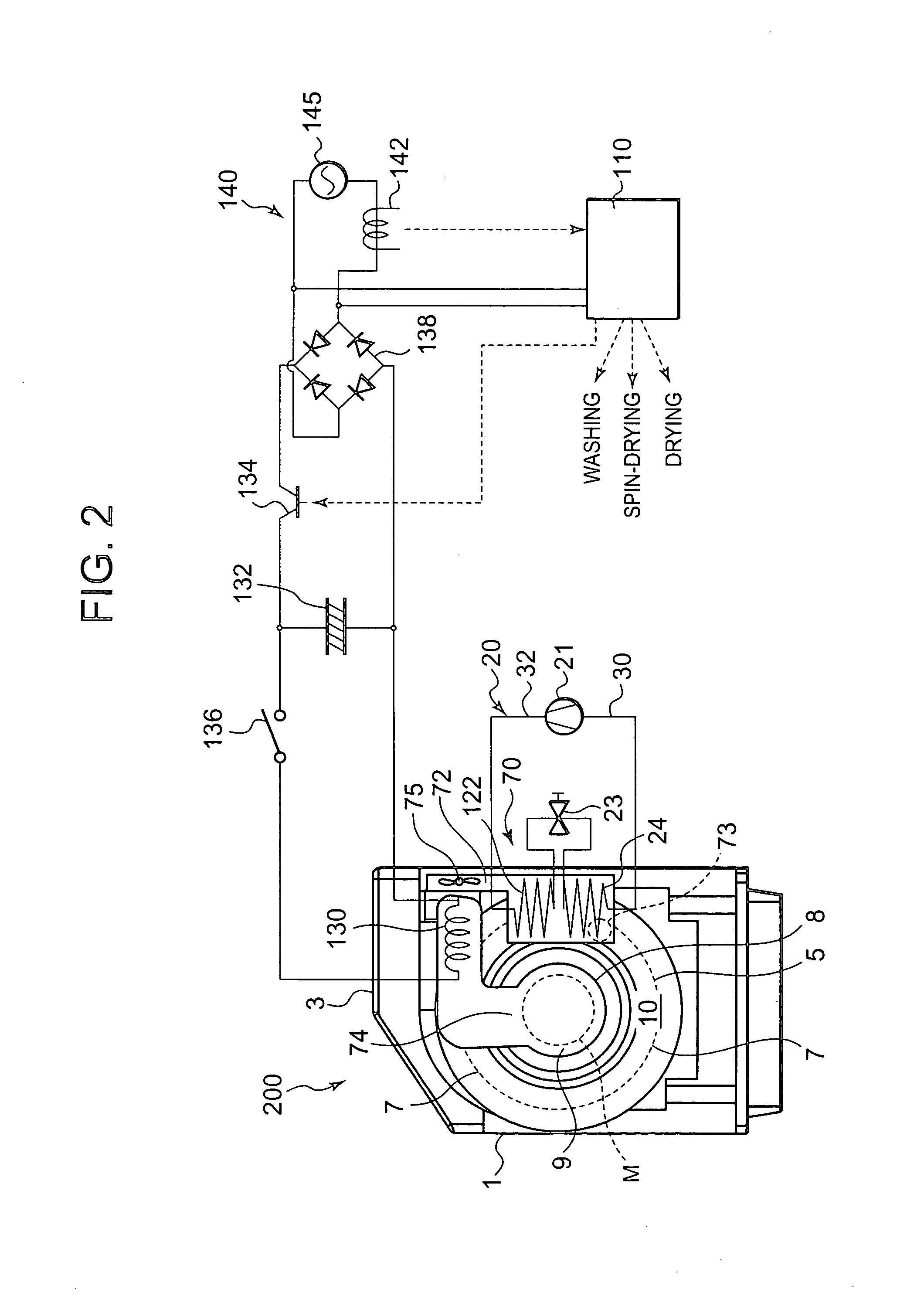
[0017] According to the present invention, the drying apparatus comprises: the accommodating chamber in which the laundry is accommodated and in which the washing operation of the laundry and the drying operation after end of the washing operation are performed; the refrigerant circuit in which the compressor, radiator, decompression device, and evaporator are successively connected to one another in the annular form via the piping; the air path for discharging the air which has exchanged the heat with the radiator into the accommodating chamber by the blower means to exchange the heat of the air passed through the accommodating chamber with the evaporator; and the control means for operating the compressor and the blower means to perform the drying operation, wherein the control means starts the operation of the compressor before entering the drying operation, so that a temperature of the radiator of the refrigerant circuit is sufficiently raised at the time when the drying operation is started, and the air discharged into the accommodating chamber can be smoothly heated. Since the temperature of the evaporator of the refrigerant circuit can also be lowered at the start of the drying operation, the moisture-containing air discharged from the accommodating chamber can be cooled and smoothly dehumidified.
[0049] Moreover, according to the present invention, additionally, the refrigerant circuit uses carbon dioxide as the refrigerant and has the supercritical pressure on the high pressure side. Therefore, the temperature of the radiator can be set at a high temperature. Accordingly, the drying air to be circulated in the accommodating chamber is maintained at the high temperature, the laundry to be dried accommodated in the accommodating chamber is dried in a shorter time, and energy consumption for use in the drying can further be reduced.

Problems solved by technology

Moreover, the high-temperature air in the accommodating chamber, by which the laundry has been dried, is exhausted to the outside.
However, when the drying operation is performed using the electric heater, the gas combustion heater or the like, outside air at a low temperature outside the accommodating chamber is used in the high-temperature air blown into the accommodating chamber, and therefore a long time is required until the laundry dries.
Therefore, energy consumption for drying the laundry to be dried increases, and there has been a problem that energy costs such as electricity and gas charges soar.
However, with the use of the heating pump, as compared with heater systems such as an electric heater and a combustion heater, a thermal capacity of a heating pump apparatus is large, and therefore there has been a problem that a long time is required from when the compressor is started and the heating coil warms at a predetermined high temperature until the moisture can be taken from the laundry in the accommodating chamber.
In this case, there has been a problem that the waste thread floating in the high-temperature / humidity air adheres to the cooling coil or the heating coil, and an air passage for circulating the air is closed, that is, clogged.
The occurrence of the clogging by the waste thread hampers normal temperature control of the cooling coil or the heating coil, and it becomes difficult to attain a purpose of smoothly performing the drying of the laundry.
To solve the problem, it is considered that a meshed filter is disposed in a circulation passage of the drying air as a method for capturing the waste thread floating in the drying air, but there has been a problem that maintenance works such as replacing and cleaning of the filter are complicated.
Moreover, generation of drying unevenness of the laundry to be dried in a rotating drum raises a problem in the drying apparatus.
However, even in this case, since a discharge direction of the drying air is limited, the drying unevenness is generated by all means.

Method used


Image

  • Drying apparatus
  • Drying apparatus
  • Drying apparatus

Examples


Embodiment Construction

[0060]FIG. 1 shows an inner constitution diagram viewed from the side surface of a washing / drying apparatus 100 which is one embodiment of a drying apparatus of the present invention. The washing / drying apparatus 100 of the embodiment is used in washing and drying laundry such as clothing. An opening / closing door 3 for inserting / removing the laundry is attached to a middle portion of the upper surface of a main body 1 forming an outer structure, and an operation panel (not shown) in which various operation switches and a display portion are disposed is disposed on the upper surface of the main body 1 beside the opening / closing door 3.

[0061] A cylindrical resin outer drum 2 capable of storing water is disposed in the main body 1, and the outer drum 2 is disposed with respect to an axis of a cylinder which is a right / left direction. Moreover, a cylindrical stainless steel inner drum 5 which serves both as a washing tank and a spin-drying tank is disposed inside the outer drum 2. The ...


PUM


Abstract

A drying apparatus having a purpose of shortening a drying time of laundry, comprising an accommodating chamber in which the laundry is accommodated, and executing a washing operation of the laundry and a drying operation after end of the washing operation in the accommodating chamber, the machine comprising: a refrigerant circuit in which a compressor, a gas cooler, an expansion valve, and an evaporator are successively connected to one another in an annular form via a piping; an air circulation path for discharging air which has exchanged heat with the gas cooler into the accommodating chamber by a blower to exchange the heat of the air passed through the accommodating chamber with the evaporator; and a control device for operating the compressor and the blower to perform the drying operation, wherein the control device starts the operation of the compressor before entering the drying operation.

Description

BACKGROUND OF THE INVENTION [0001] The present invention relates to a drying apparatus including an accommodating chamber for accommodating things to be dried, or laundry, in which a drying operation of the things to be dried is executed, or a washing operation of the laundry and a drying operation after end of the washing operation are performed in the accommodating chamber. [0002] In recent years, there has been provided a drying apparatus (washing / drying apparatus) for automatically performing washing to drying in an accommodating chamber in which laundry is accommodated. The drying apparatus generally performs a washing operation including a plurality of different processes such as washing, rinsing, and spin-drying, and a drying operation for drying the laundry spin-rinsed in the processes. [0003] Here, in the drying operation, an electric heater or a gas combustion heater has heretofore been used as a heat source. After heating outside air by the electric heater or the combusti...

Claims


Application Information

Patent Timeline
IPC IPC(8): D06F58/20
CPCD06F58/206
Inventor TADANO, MASAYAAKIYAMA, SHINICHIKOUMOTO, NOBUOKAWABATA, TORUKUBO, RYOKOMUKAIYAMA, HIROSHITOMOCHIKA, KAZUYOSHIONO, KOJI
Owner QINGDAO HAIER WASHING MASCH CO LTD
Learn More