Apparatus for manufacturing band plate

a technology of band plate and accessory, applied in the direction of manufacturing tools, metal rolling arrangement, counter-pressure devices, etc., can solve problems such as heat crown phenomenon, and achieve the effect of small resistan

Active Publication Date: 2005-03-03
IHI CORP
View PDF5 Cites 10 Cited by
  • Summary
  • Abstract
  • Description
  • Claims
  • Application Information

AI Technical Summary

Benefits of technology

[0021] According to the aforementioned configuration of the present invention, because the work roll is provided with the reverse taper portion, on which roll diameters gradually increase towards the barrel end portion thereof corresponding to the edge drop part, and the upper or lower work roll is composed to be shiftable individually in the axial direction of the roll, even if edge drops at both ends of the slab material differ greatly from each other, the shape of the rolled plate can be maintained under the preferred conditions by separately axially shifting the upper and lower work rolls.
[0022] Also, because the backup roll is provided with the escape portion at which roll diameters gradually decrease towards an end of the axis of the roll within the shiftable range of the work roll, so that the backup roll does not come into contact with the reverse taper portion of the work roll, the reverse taper portion of the work roll can be prevented from interfering with the backup roll, so the work roll can be axially shifted with a small resistance.

Problems solved by technology

However, the aforementioned continuous casting machine 50 of a double-roll type suffers from a heat crown phenomenon at the casting rolls during casting, because of the long casting roll 51.

Method used


Image

  • Apparatus for manufacturing band plate
  • Apparatus for manufacturing band plate
  • Apparatus for manufacturing band plate

Examples


first embodiment

[0034]FIG. 5 shows the apparatus for manufacturing a band plate according to the present invention; FIG. 6 shows another operating status of the apparatus in FIG. 5.

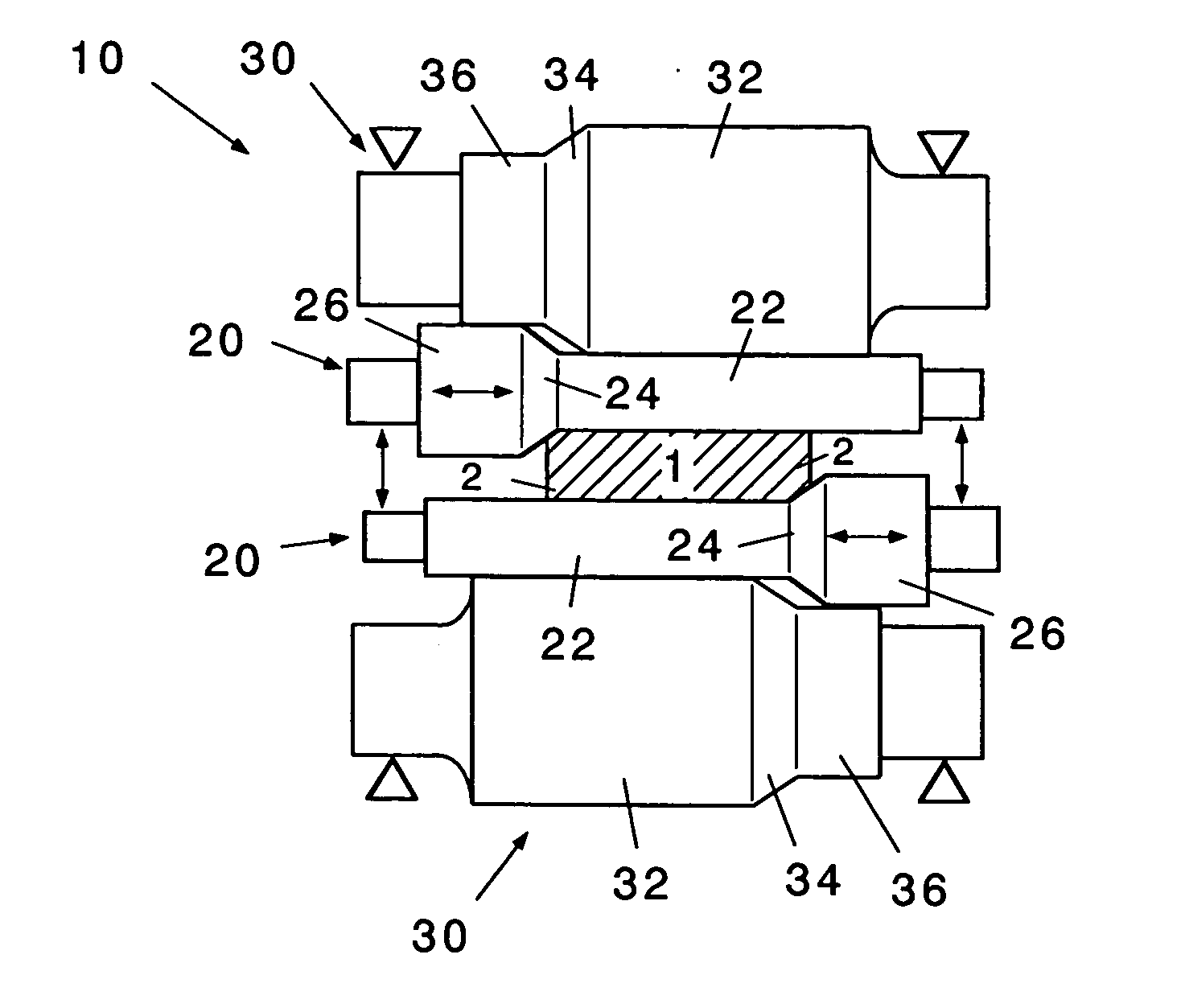
[0035] The apparatus for manufacturing a band plate of the present invention is preferably provided with a rolling mill 10 arranged downstream from a strip caster. In FIG. 5, this rolling mill 10 is composed of a pair of upper and lower work rolls 20 and a pair of upper and lower backup rolls 30.

[0036] The work roll 20, in a pair of upper and lower rolls, is provided with a rolling portion 22 formed in a slim cylinder, and can press a slab material 1 with edge drop portions 2 at both ends thereof. The backup roll 30, in a pair of upper and lower rolls, is shaped to have a backup portion 32 in a small cylinder, and contacts the non-rolling side surface of the work roll 20 in the pair, and can protect the work roll 20 from being bent and deformed. The backup roll 30 is supported by bearings, illustrated as triangles in FI...

second embodiment

[0047]FIG. 7 shows the apparatus for manufacturing a band plate according to the present invention, and FIG. 8 shows another operation state of the apparatus shown in FIG. 7.

[0048] In this embodiment, the expansion diameter portion 26 of the work roll and the contraction diameter portion 36 of the backup roll are in contact with each other. Therefore, in this example, expansion and contraction diameter portions 26, 36 functions, differently from the first embodiment. Other configuration details are the same as those in the first embodiment.

[0049]FIG. 7 is a view in which shifting strokes of upper and lower work rolls 20 are the same for this apparatus; and FIG. 8 represents a case where shifting strokes of upper and lower work rolls 20 differ from each other.

[0050] In FIG. 7, like the operation state of the first embodiment, the depth of rolling the center portion of the slab is adjusted by the rolling load applied from the back up roll 30, and the depth of the rolling of edge dro...


PUM

PropertyMeasurementUnit
widthaaaaaaaaaa
diameteraaaaaaaaaa
diameteraaaaaaaaaa

Abstract

An apparatus for manufacturing a band plate has a rolling mill that includes a pair of upper and lower work rolls that roll a slab material having edge drop portions at both ends thereof, and a pair of backup rolls that contact non-rolling side surfaces of the pair of upper and lower work rolls, respectively to prevent the work rolls from being deformed. The work roll includes a reverse taper portion where a roll diameter gradually increases towards a barrel end portion thereof corresponding to the edge drop portion. The upper and lower work rolls are configured to be shiftable individually in the axial direction thereof. The backup roll includes an escape portion whose diameter gradually decreases towards an axial end thereof so as not to contact the reverse taper portion of the work roll, within a shifting range of the work roll.

Description

BACKGROUND OF THE INVENTION [0001] 1. Technical Field of the Invention [0002] The present invention relates to an apparatus for manufacturing a band plate that presses edge drop portions at both ends of a plate before rolling, together with a center part of the plate, and leaves edge drops on the plate after rolling. [0003] 2. Description of the Related Art [0004]FIGS. 1A and 2 are schematic views of a continuous casting machine of a double-roll type. As shown in these figures, when a slab of a predetermined width is manufactured using a continuous casting machine 50 (strip caster), casting metal in a molten state is passed through two rolls 51 (casting rolls) that rotate in reverse directions. Casting rolls 51 are separated by a predetermined gap that is appropriate for forming the thickness of a slab plate, and are installed in parallel and horizontally. [0005] Molten metal for casting is supplied to a pouring basin formed between side dams 53 disposed between both ends of the cas...

Claims


Application Information

Patent Timeline
Patent Type & Authority Applications(United States)
IPC IPC(8): B21B1/00B21B1/02B21B1/46B21B13/02B21B13/14B21B27/02B21B29/00B21B31/18B22D11/06
CPCB21B1/026B21B1/463B21B13/142B21B27/02B21B29/00B21B2001/028B21B2013/025B21B2027/022B21B2263/02B21B2269/04B21B2269/14
Inventor HONJO, HISASHIIWASAKI, TAKAYUKI
Owner IHI CORP
Why Eureka
Try Eureka