Unipolar electrostatic quadrupole lens and switching methods for charged beam transport

a quadrupole lens and electrostatic quadrupole technology, applied in the field of ion implantation devices, can solve the problems of beam current loss, particularly high loss at lower energies, and substantial loss of beam current, and achieve the effect of reducing beam current loss and extending the operation rang

Active Publication Date: 2005-03-03
PHARMACOPEIA DRUG DISCOVERY +1
View PDF20 Cites 30 Cited by
  • Summary
  • Abstract
  • Description
  • Claims
  • Application Information

AI Technical Summary

Benefits of technology

[0009] The present invention mitigates loss of beam current, particularly for low energy ion implants. The present invention utilizes electrostatic quadrupole lenses, each energized by a unipolar power supply rather than a bipolar supply, to transport a low energy ion beam through the linear accelerator section of an ion im

Problems solved by technology

Generally, there is a substantial loss of beam current as the dopant ions pass through the acceleration system.
This loss is particularly high at lower energies.
Such loss of beam current can increase the cost, complexity, and

Method used


Image

  • Unipolar electrostatic quadrupole lens and switching methods for charged beam transport
  • Unipolar electrostatic quadrupole lens and switching methods for charged beam transport
  • Unipolar electrostatic quadrupole lens and switching methods for charged beam transport

Examples


Embodiment Construction

[0019] The present invention will now be described with reference to the attached drawings, wherein like reference numerals are used to refer to like elements throughout. It will be appreciated by those skilled in the art that the invention is not limited to the exemplary implementations and aspects illustrated and described hereinafter.

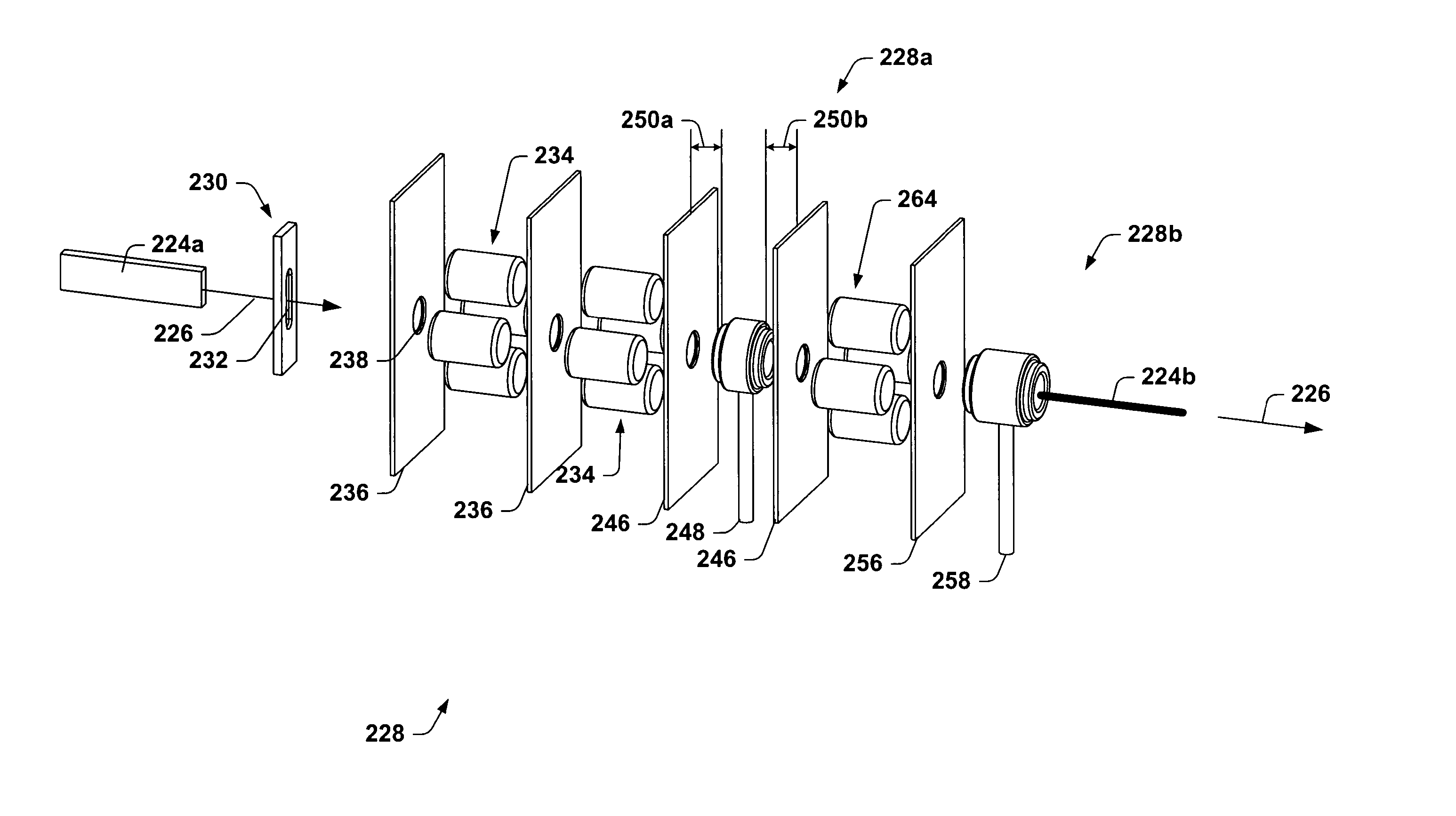
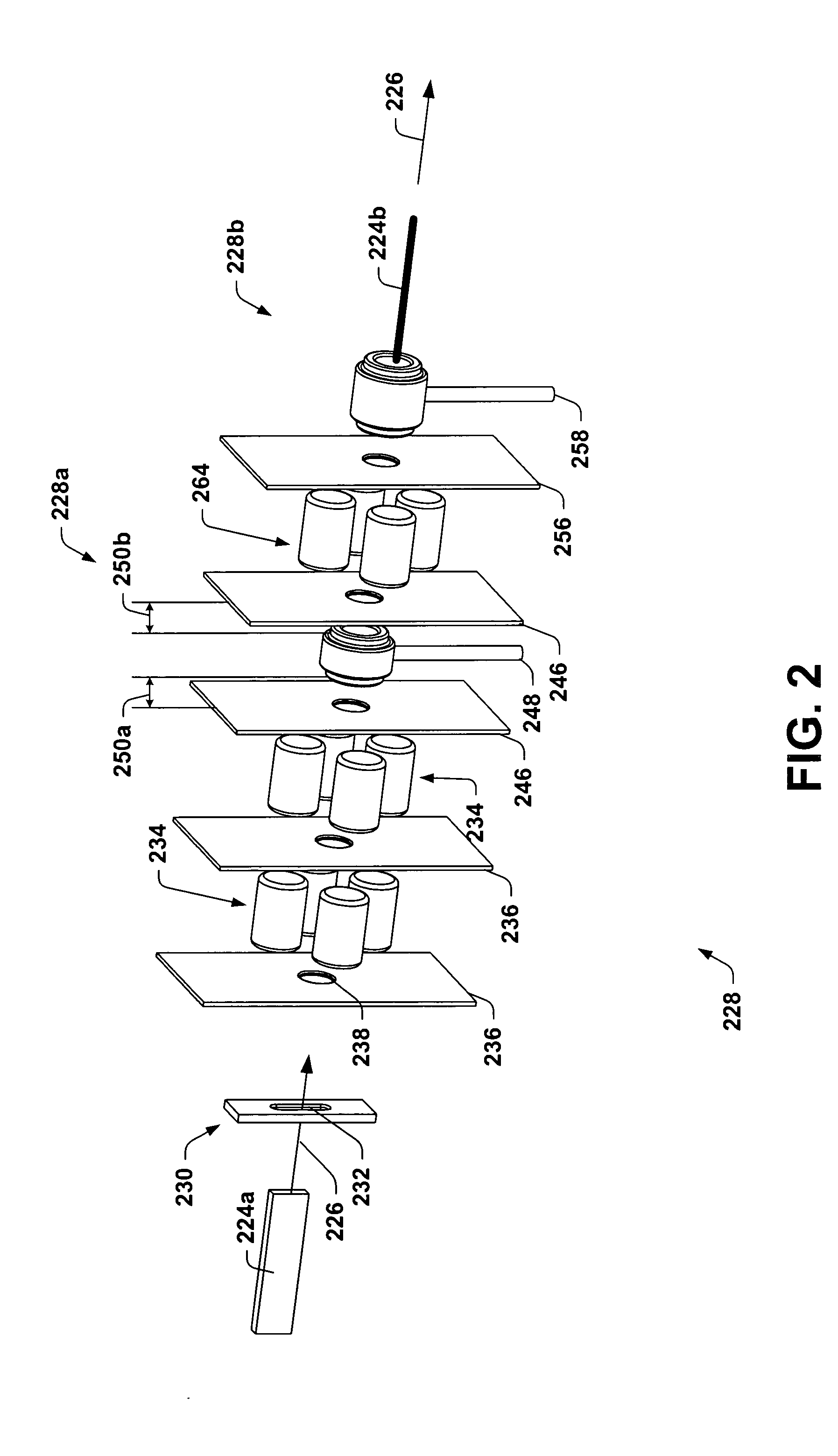
[0020] The present invention facilitates ion implantation by reducing degradation of beam current through the linear accelerator section of a high energy implanter. A series of unipolar quadrupole lenses are employed instead of bipolar quadrupole lenses. The use of the unipolar quadrupole lenses mitigates beam current loss and can extend an operation range of the ion implantation system.

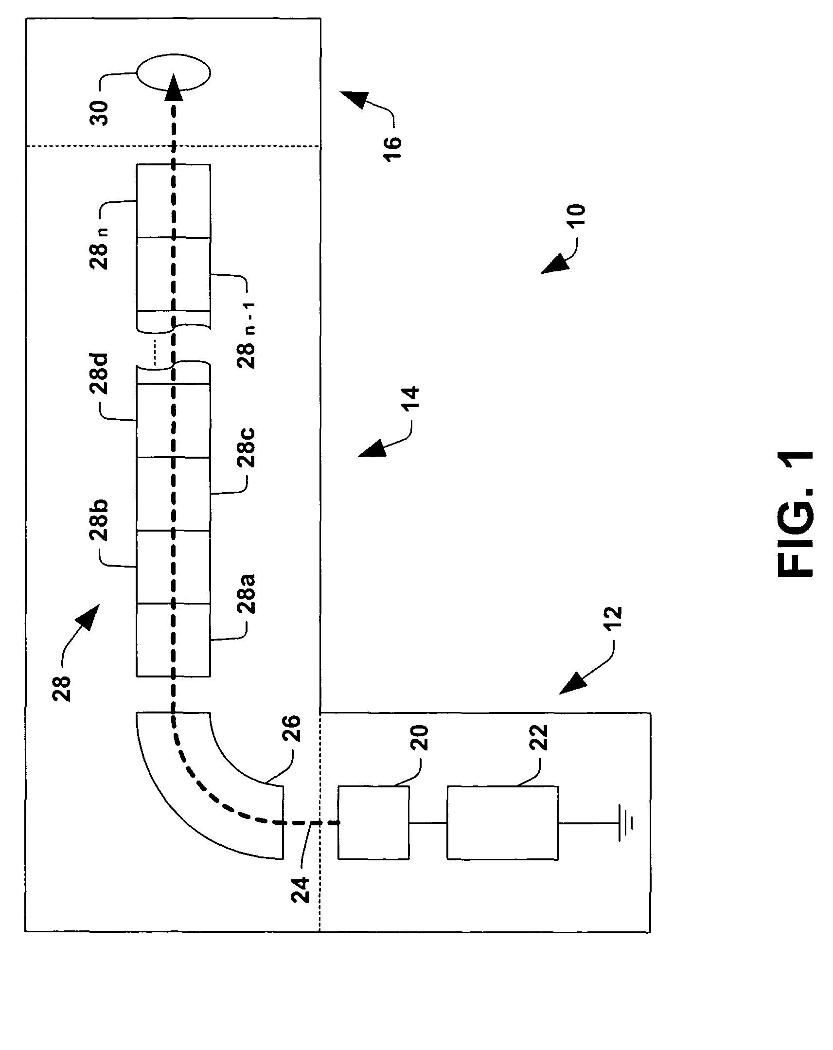
[0021] Beginning with FIG. 1, a diagram of an exemplary high energy ion implantation system 10 in accordance with an aspect of the present invention is illustrated. The system 10 has a terminal 12, a beamline assembly 14, and an end station 16. The terminal 12 inclu...


PUM


Abstract

The present invention mitigates loss of beam current, particularly for low energy ion beam transport. The present invention employs unipolar electrostatic quadrupole lenses instead of conventional dual positive and negative potential (bipolar) quadrupole lenses as beam focusing elements within a linear accelerator, reducing beam current losses therein. In addition, the present invention also includes systems and methods for switching between bipolar wiring and unipolar wiring.

Description

FIELD OF INVENTION [0001] The present invention relates generally to ion implantation devices, and, more particularly, to a unipolar electrostatic quadrupole lens and use of the lens usable within an ion implantation system. BACKGROUND OF THE INVENTION [0002] Ion implantation is a process that is employed in semiconductor device fabrication to selectively implant dopant into semiconductor and / or wafer material. For ion implantation, dopant atoms / molecules are ionized and isolated, accelerated, formed into a beam, and swept across a wafer. The dopant ions physically bombard the wafer, enter the surface and come to rest below the surface. [0003] An ion implantation system is a collection of sophisticated subsystems, each performing a specific action on the dopant ions. Dopant elements, in gas or solid form, are positioned inside an ionization chamber and ionized by a suitable ionization process. In one exemplary process, the chamber is maintained at a low pressure (vacuum). A filament...

Claims


Application Information

Patent Timeline
IPC IPC(8): H01J37/12H01J37/153H01J37/317
CPCH01J37/12H01J37/153H01J2237/04924H01J2237/04735H01J2237/04737H01J37/3171H01L21/265
Inventor DIVERGILIO, WILLIAM F.HUANG, YOUNGZHANG
Owner PHARMACOPEIA DRUG DISCOVERY
Why Eureka
Try Eureka