Traffic light signal system using radar-based target detection and tracking

a traffic light signal and target detection technology, applied in the field of traffic control indicators, can solve the problems of system failure in field trials, video cameras only detecting the position and velocity of vehicles, and longer green light delays, so as to reduce reduce the chance of accidents and pavement damage, and save energy

Inactive Publication Date: 2005-03-03
POWER SIGNAL TECH +1
View PDF55 Cites 144 Cited by
  • Summary
  • Abstract
  • Description
  • Claims
  • Application Information

AI Technical Summary

Benefits of technology

The present invention achieves technical advantages as an improved radio frequency (RF) emission, or radar, system integrated within a traffic light signaling system adapted to determine, among other things, (1) in advance of an RLR condition, the likely occurrence of an RLR condition, (2) the need to provide a LTW to a driver seeking to make a ULT, and (3) the nature of an approaching flow of object / vehicle targets and dynamically adjust the traffic signals so as to reduce accidents and pavement damage and conserve energy. The present invention is an improved method and apparatus to implement each of the foregoing functionalities, together, in parts or individually.
More specifically, the determination of a possible RLR condition can be used to trigger an RLH circuit to hold the cross-traffic red light until it is determined that conditions are safe to provide a green light to cross traffic. The determination of a possible collision between an oncoming vehicle with a vehicle making an ULT can be used to trigger an LTW circuit to warn the driver making the left hand turn of oncoming traffic. The LTW is turned off when the LTW circuit determines that the danger has passed. The determination of the nature of the approaching flow of object / vehicle targets can be used to trigger a GLE circuit that is operable to maintain a green traffic signal until all of the object / vehicle targets in the flow have exited the intersection. In this manner, GLE can dynamically adjust the timing of the traffic signals so as to reduce the chance of accidents and pavement damage.
Implementation of the foregoing functionalities requires the use of an RF emission and sensing apparatus, such as radar. Radar transmitters using modulated signals require receivers adapted to sense the reflected signals. The radar transceiver of the present invention uses a Linear Frequency Modulated Continuous Wave (“LFM-CW”) RF signal transmission and a multi-stage spectral processing algorithm in the receiver to determine the range, velocity, and return-signal magnitude of the illuminated targets during a very short observation interval. In one embodiment, the target information collected during each observation interval is passed to a high-level tracker (“HLT”) that is capable of tracking the behavior of targets over a longer period of time. The HLT can validate the presence of targets, eliminate invalid observations, and predict the future behavior of targets. The radar / traffic processor collects approaching object / vehicle target information from the HLT and traffic signal state information from the traffic signal system to determine whether to trigger the RLH, GLE or LTW functionalities. An HLT may be integrated in the radar / traffic process.
An advantage of the system and method of the present invention is that the modulated radar signal can be used to determine the range and velocity of a number of targets over a large region with high accuracy. Furthermore, the signal processing aspects of the present invention can be used in combination with innovative algorithmic methods for determining whether to trigger the RLH, GLE or LTW functionalities.

Problems solved by technology

These green light delays may be longer in higher-speed intersections where RLR object / vehicle targets might travel in excess of 70 mph.
However, these systems failed in field trials since they are based on sensors that do not provide adequate information to a RLH decision algorithm.
Disadvantageously, the video cameras could only detect the position and velocity of a vehicle within a few hundred feet of the video camera mounted in close proximity to the traffic signal.
As a result, this system is unable to prevent most RLR accidents.
However, disadvantageously, these sensors simply detect the presence of a vehicle above them.
Thus, vehicles can only be detected at places in the roadway where sensors are installed resulting in a limited view of the incoming traffic.
Furthermore, these loop sensors are expensive to install and maintain.
A system employing one or two loop detectors on an intersection approach is not capable of making consistently accurate RLH decisions.
This is impractical in terms of installation cost, reliability, and maintenance cost.
Nevertheless, there are times when a sufficient break in traffic is not available.
In addition, some drivers will stop abruptly when the light turns yellow causing trailing vehicles to rear end them.
For instance, large trucks that are forced to stop at the intersection present a significant loading on the pavement for the duration of the red light, with the result that cities are required to make pavement repairs more often for intersections that carry a high volume of truck traffic.
As noted above, these sensors are expensive to install and maintain, and furthermore, are limited in their ability to detect information about vehicles as these sensors simply detect the presence and speed of a vehicle.
Because vehicles can only be detected at places in the roadway where sensors are installed, a limited view of the incoming traffic is presented.
Algorithms that determine GLE time will perform better when more sensors are present, however, the number of conventional sensors required make such a system inefficient.
In addition, there are many accidents each year resulting from drivers of vehicles making unprotected left turns (referred to herein as “ULT”) across approaching, oncoming traffic or crossing traffic.
Due to the geometry of certain intersections, the presence of cars in the opposing left turn lane can block the view of drivers attempting to make a left turn.
LTW senses that a driver in an oncoming or crossing object / vehicle target is going to approach the intersection within a certain time frame such that the left turning vehicle is put at risk if it is in the intersection.
Preferably, the signal would only warn drivers that vehicles are approaching and that conditions are dangerous for turning, not inform drivers that it is safe to turn.
Sensors such as loop detectors in the pavement can provide a limited amount of information.

Method used


Image

  • Traffic light signal system using radar-based target detection and tracking
  • Traffic light signal system using radar-based target detection and tracking
  • Traffic light signal system using radar-based target detection and tracking

Examples


Embodiment Construction

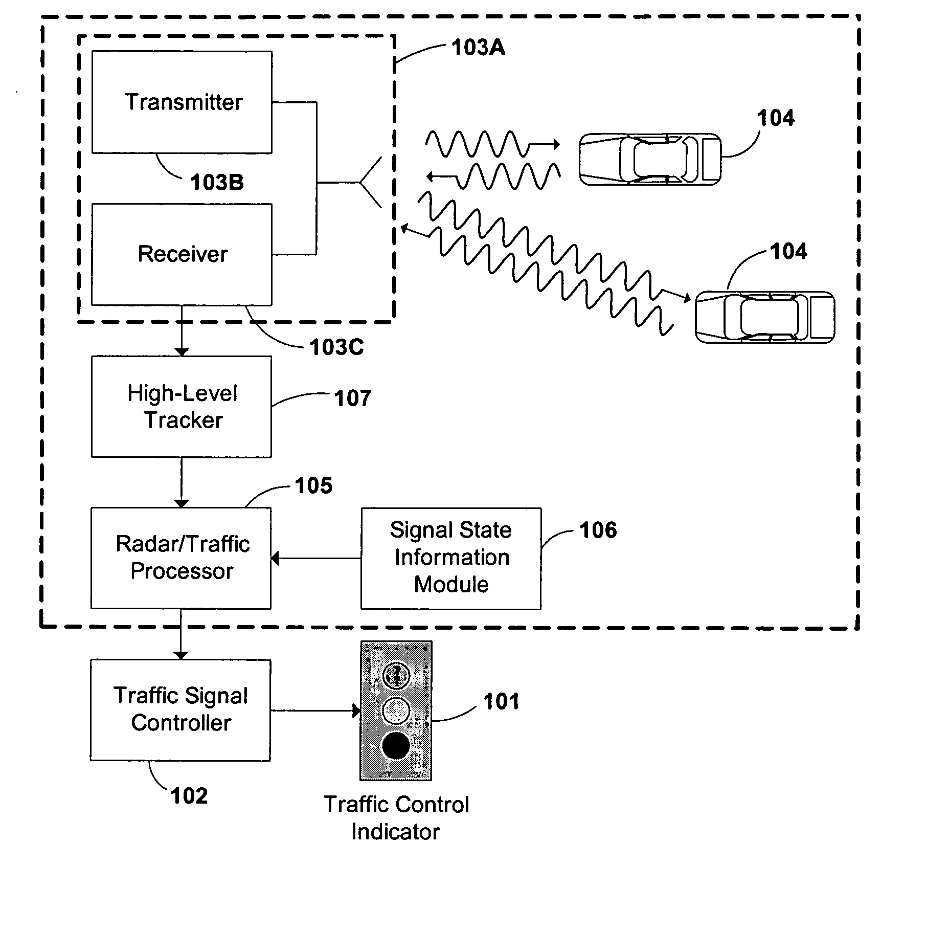
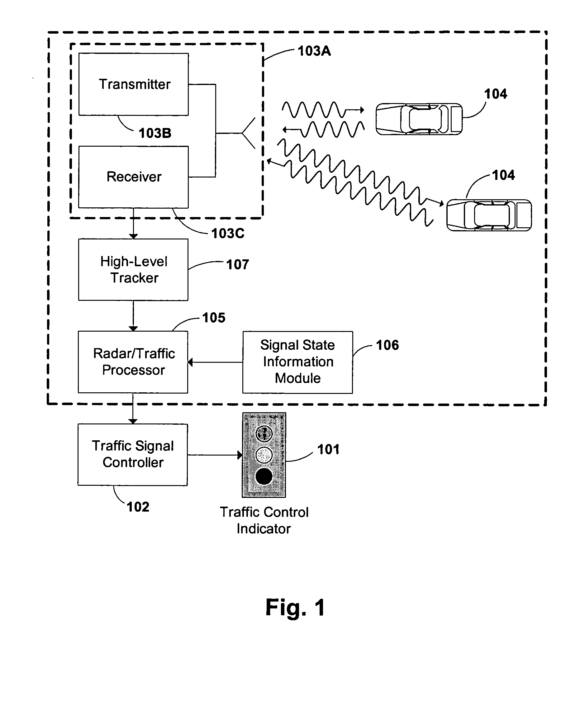
A block diagram of one exemplary embodiment of the present invention is shown in FIG. 1. The system is implemented using at least one traffic control indicator 101 adapted to control or alert traffic at a roadway intersection. A traffic signal controller 102 coupled to the traffic control indicator 101 is adapted to change the states of the traffic control indicator 101, and is conventionally located in a controller cabinet near the intersection. An RF emissions apparatus, such as a radar 103A, is operable to transmit signals using transmitter 103B toward, and receive signals from, a plurality of object / vehicle targets 104. Object / vehicle targets 104 may include cars, trucks, motorcycles, bicycles, pedestrians, or any other type of object commonly found in or traversing an intersection. A radar / traffic processor 105 adapted to receive processed information from the RF emissions receiver apparatus, such as a receiver 103C, is coupled to both the traffic signal controller 102 and to a...


PUM


Abstract

A novel system and method of integrating an RF emissions device, such as a radar system (103A), within a traffic control indicator (101) system. The system and method determines, using LFM-CW radar signals (201) and a multi-stage spectral processing algorithm (600), if one or more object / vehicle targets will enter an intersection and comprises receiving a radar echo response (203) indicating the object / vehicle target (104) is approaching the intersection, receiving range and velocity of the object / vehicle targets (104), and based on the receiving, determining if the object / vehicle target (104) will enter the intersection. The system and method can programmatically be configured to activate red-light-hold, green-light-extension, or left-turn-warning.

Description

FIELD OF THE INVENTION The present invention is directed to traffic control indicators for controlling automobile traffic in an intersection, and more particularly to radar transceivers used in combination with traffic lights for controlling light signals as a function of vehicles approaching or entering an intersection. As used herein, traffic control indicator means any indicator used to control, notify, or alert vehicle or pedestrian traffic, including but not limited to traffic signals, traffic lights, lights, flashing lights, LED arrays, messages, and other vehicle or pedestrian traffic warning and control indicators. Likewise, the use of a term such as light, light signal, traffic signal and the like is not meant to be limiting, but rather is intended to cover any type of traffic control indicator. The use of terms to generally describe components of the invention, such as lights, is not meant to be limiting. For example, the term lights, means any indicator, such as light bu...

Claims


Application Information

Patent Timeline
Patent Type & Authority Applications(United States)
IPC IPC(8): G01S7/00G01S7/41G01S13/34G01S13/72G01S13/92G01S15/88G08G1/07
CPCG01S7/003G01S7/41G01S13/343G08G1/07G01S13/92G01S15/88G01S13/726
Inventor HUTCHISON, MICHAEL C.PAUTLER, JAMES A.SMITH, MARK A.
Owner POWER SIGNAL TECH
Why Eureka
Try Eureka