Ultra high resolution radar with active electronically scanned antenna (AESA)

a high-resolution, radar technology, applied in the direction of antennas, modular arrays, missiles, etc., can solve the problems of no traditional phase shifters or true time delay devices, the scan strategy of array antennas is complicated and difficult to realize, and the inability to realize traditional radar scan strategies

Inactive Publication Date: 2005-03-03
VOLMAN ALLA
View PDF5 Cites 33 Cited by
  • Summary
  • Abstract
  • Description
  • Claims
  • Application Information

AI Technical Summary

Problems solved by technology

The array antenna scan strategy can be very complicated and difficult to realize because of the inadequate phase shifter accuracy or scan speed, extra mass, large size of the elements providing the beams steering, and rather high cost of used technologies.
There are no traditional phase shifters or true time delay devices.
The main disadvantage is the

Method used

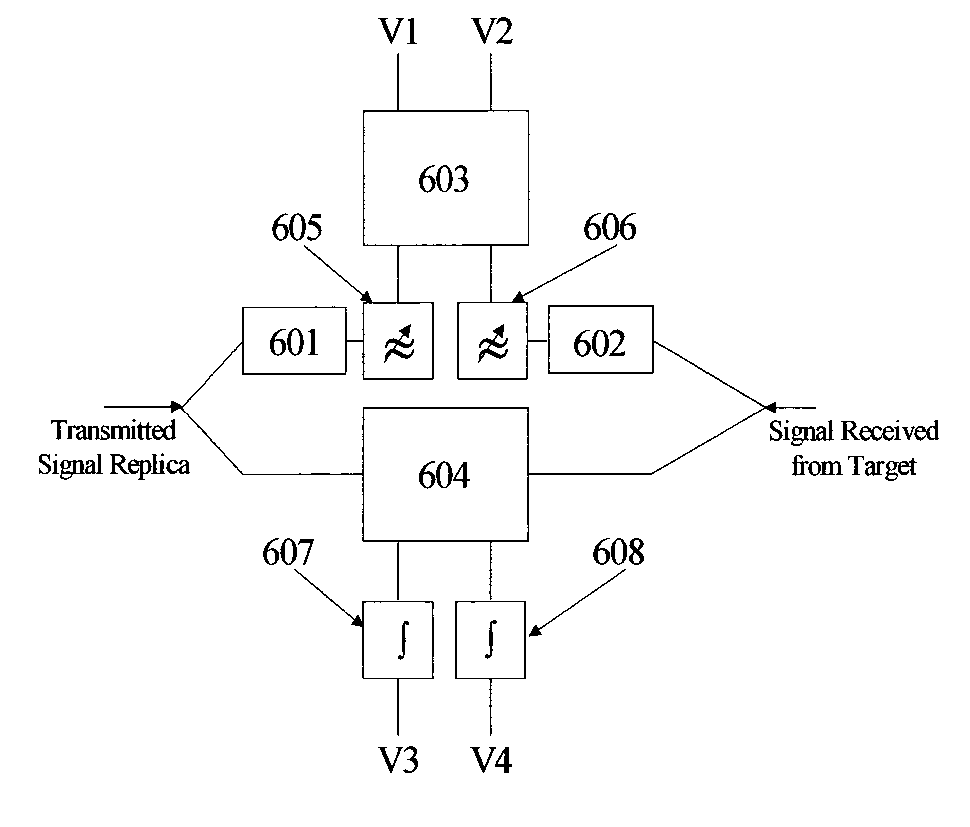
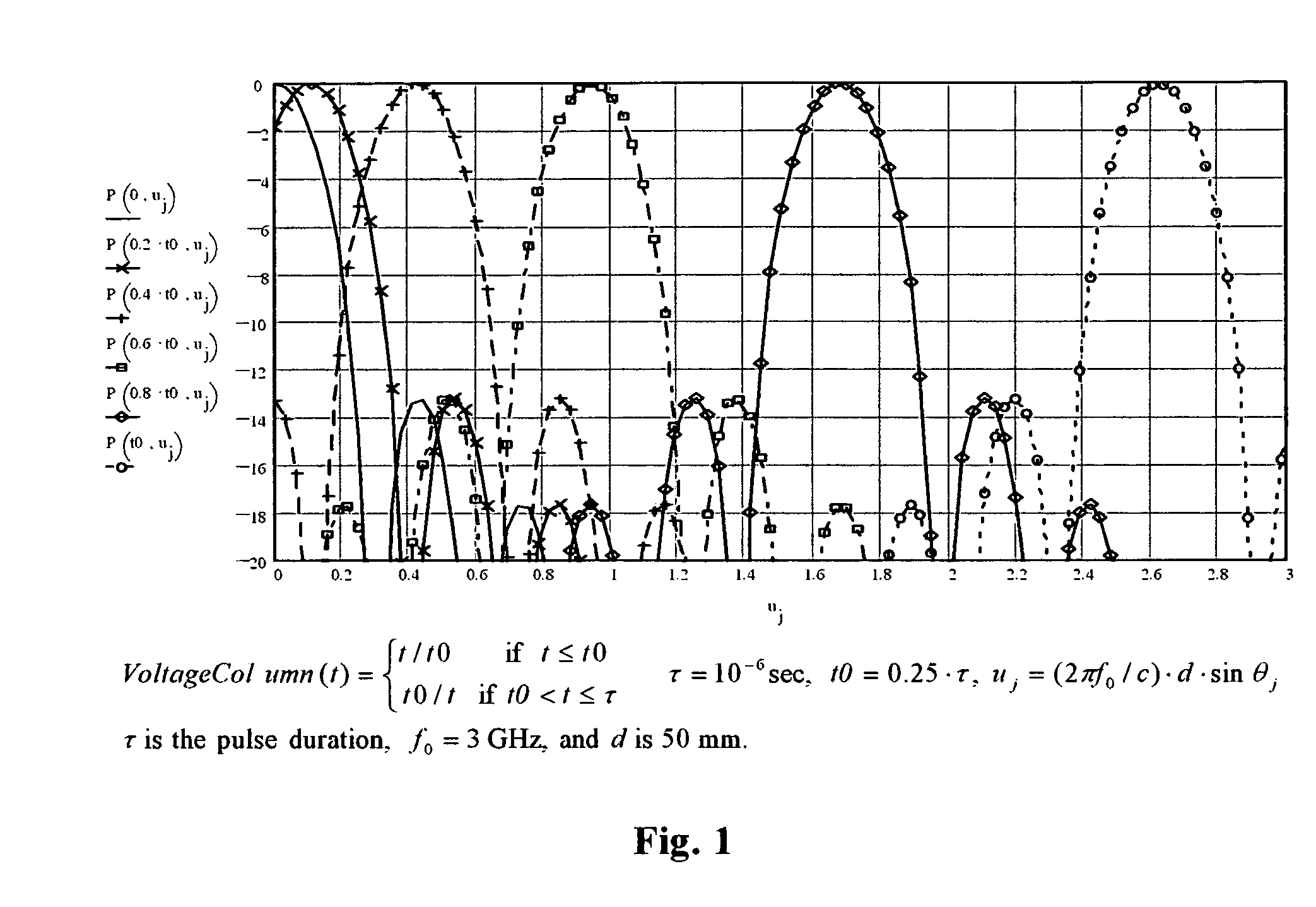
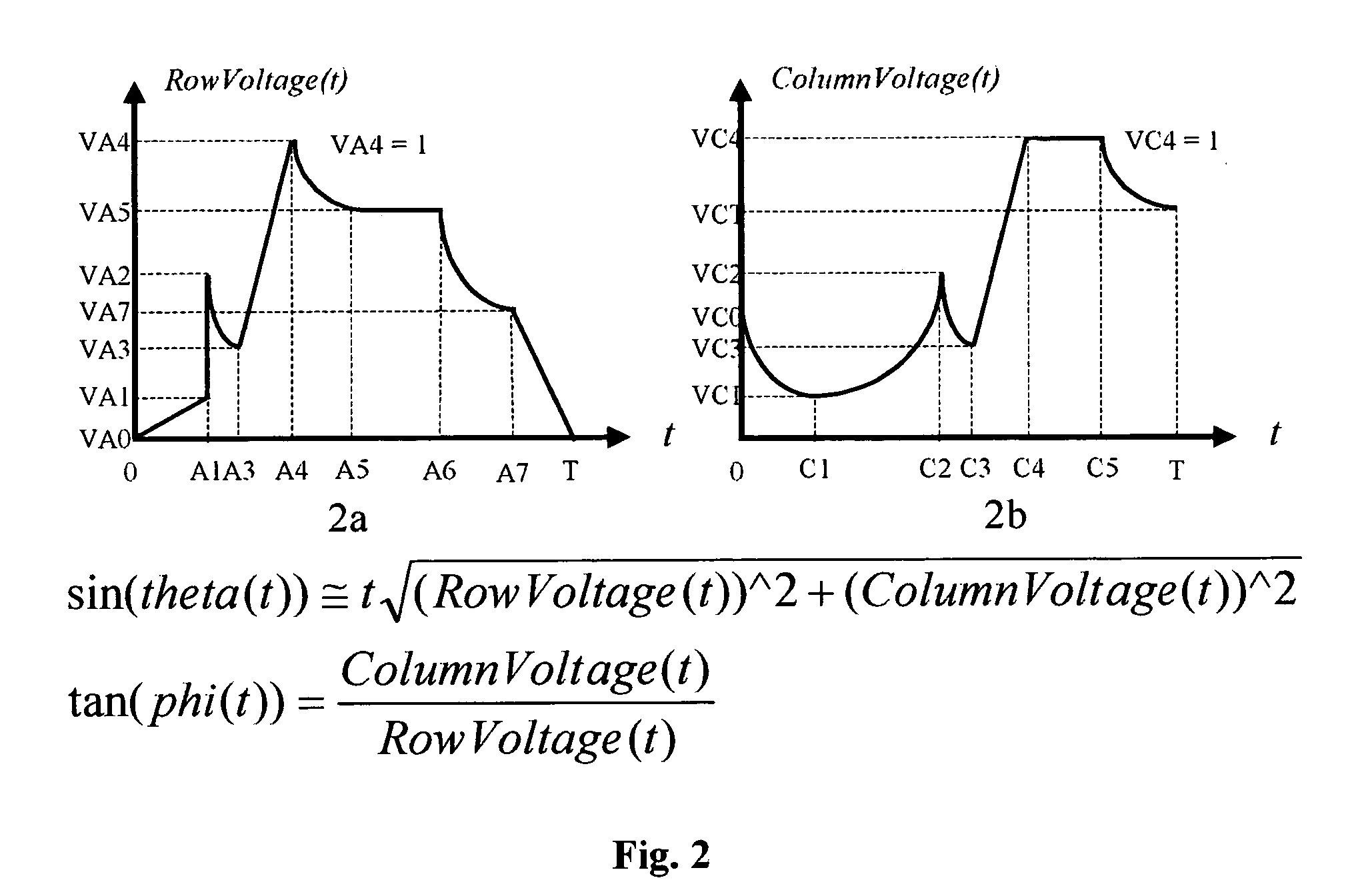

Image

  • Ultra high resolution radar with active electronically scanned antenna (AESA)
  • Ultra high resolution radar with active electronically scanned antenna (AESA)
  • Ultra high resolution radar with active electronically scanned antenna (AESA)

Examples


Embodiment Construction

The present invention is now described more fully hereinafter with reference to the accompanying drawings that show a preferred embodiment of the present invention. The present invention, however, may be embodied in many different forms and should not be construed as limited to embodiments set forth herein. Appropriately, embodiments are provided so that this disclosure will be thorough, complete and fully convey the scope of the present invention.

According to embodiments of the present invention, each transmitting element of said AESA radiates pulse signals with different waveform, so the phase and power spectrum of signal radiated by AESA and illuminated target / targets becomes the function of the range, elevation and azimuth angle. With proper processing the receiver can decode this vital data. This novel and important feature of the invention presented, allows get a stationary beam position, any conceivable scan pattern, high signal-to-noise ratio in tracking mode, and as the ...


PUM


Abstract

An ultra-high resolution radar system and technique for transmit or receive AESAs or that yields performance substantially greater than, that of conventional radar systems and techniques while being simple and inexpensive to manufacture. The device comprises the transmit/receive flat or conformal AESA or AESAs steering beam or beams non-depressively, and creating RF FM modulated pulse signals of identical shape and duration through a resistive multiport voltage divider/dividers electrically connected VCOs, RF mixers and STALO or any other narrow-band or wide-band source of RF signals, and to a plurality of radiating elements in order to generate signals providing simultaneously the required beam or beams azimuth and elevation steering electronically and receiving target-echo return pulse signals.

Description

BACKGROUND OF THE INVENTION 1. Field of the Invention This present invention relates generally to ground base, airborne, spaceborne, missiles, ship based scanning radars, or other sensing systems for experimental, military, or commercial applications, and more particularly the present invention relates to a multifunctional scanning radar with AESA or AESAs providing extremely flexible electronic beam / beams steering without conventional variable phase shifters or time delay devices and improved angle and range resolution, clatter and jamming performance. 2. Description of the Prior Art Modern radar, communication, and sensing systems are finding increasing use for a array antenna assembled from a great many similar radiating elements, each element being individually controlled in phase and amplitude. A salient advantage of an array antenna is the ability to scan the beam or many beams very fast electronically without moving the mass of the array antenna. The accurate measurement ...

Claims


Application Information

Patent Timeline
IPC IPC(8): G01S13/02G01S13/28H01Q21/00
CPCG01S13/282H01Q21/0025G01S2013/0254
Inventor VOLMAN, ALLA
Owner VOLMAN ALLA
Why Eureka
Try Eureka