Maskless lithography systems and methods utilizing spatial light modulator arrays

a lithography and spatial light technology, applied in the field of lithography, can solve the problems of increasing the cost and time of reticle manufacture, the reticle can only be used for a certain period of time before being worn out, and the routine cost of further costs

Inactive Publication Date: 2005-03-03
ASML HLDG NV
View PDF31 Cites 20 Cited by
  • Summary
  • Abstract
  • Description
  • Claims
  • Application Information

AI Technical Summary

Benefits of technology

[0014] The present invention provides a maskless lithography system. The system can include an illumination system, an object, spatial light modulators (SLMs), and a controller. The SLMs can pattern light from the illumination system before the object receives the light. The SLMs can include a leading set and a trailing set of the SLMs. The SLMs in the leading and trailing sets change based on a scanning direction of the object. The controller can generate control signals to the SLMs based on at least one of light pulse period information, physical layout information about the SLMs, and scanning speed of the object.

Problems solved by technology

These reticles are becoming increasingly costly and time consuming to manufacture due to the feature sizes and the exacting tolerances required for small feature sizes.
Also, a reticle can only be used for a certain period of time before being worn out.
Further costs are routinely incurred if a reticle is not within a certain tolerance or when the reticle is damaged.
Thus, the manufacture of wafers using reticles is becoming increasingly, and possibly prohibitively expensive.
This results in low throughput (number of pixels packed into an individual optical field / number of repeat passes required over the substrate) and increased time to fabricate devices.
Furthermore, using only one SLM requires more pulses of light or more exposure time to increase gray scale.
This can lead to unacceptably low levels of throughput.

Method used


Image

  • Maskless lithography systems and methods utilizing spatial light modulator arrays
  • Maskless lithography systems and methods utilizing spatial light modulator arrays
  • Maskless lithography systems and methods utilizing spatial light modulator arrays

Examples


Embodiment Construction

[0029] Overview

[0030] While specific configurations and arrangements are discussed, it should be understood that this is done for illustrative purposes only. A person skilled in the pertinent art will recognize that other configurations and arrangements can be used without departing from the spirit and scope of the present invention. It will be apparent to a person skilled in the pertinent art that this invention can also be employed in a variety of other applications.

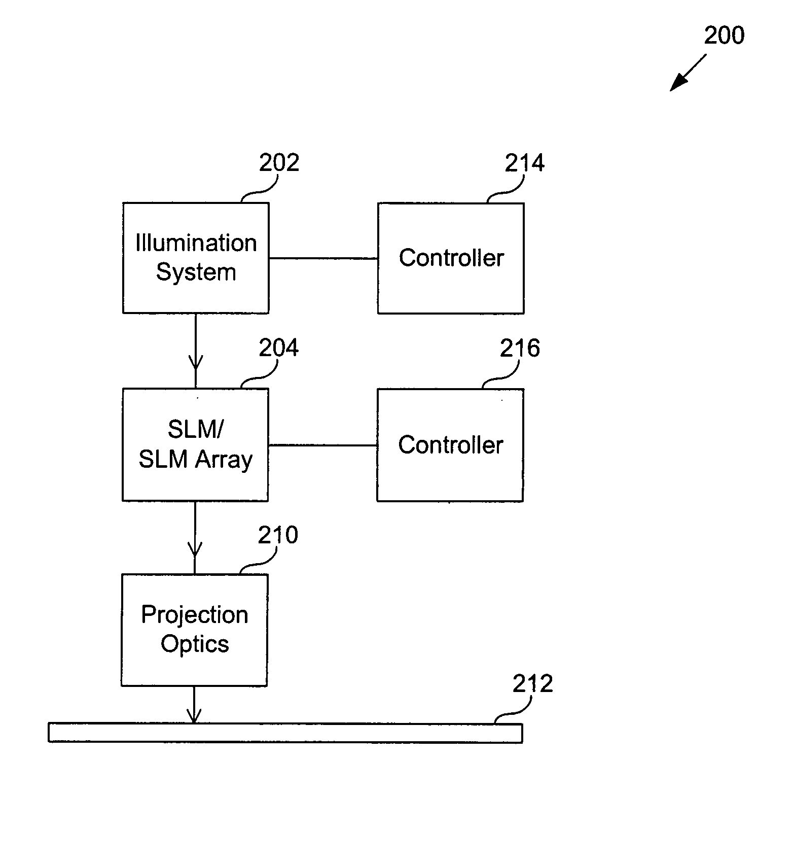
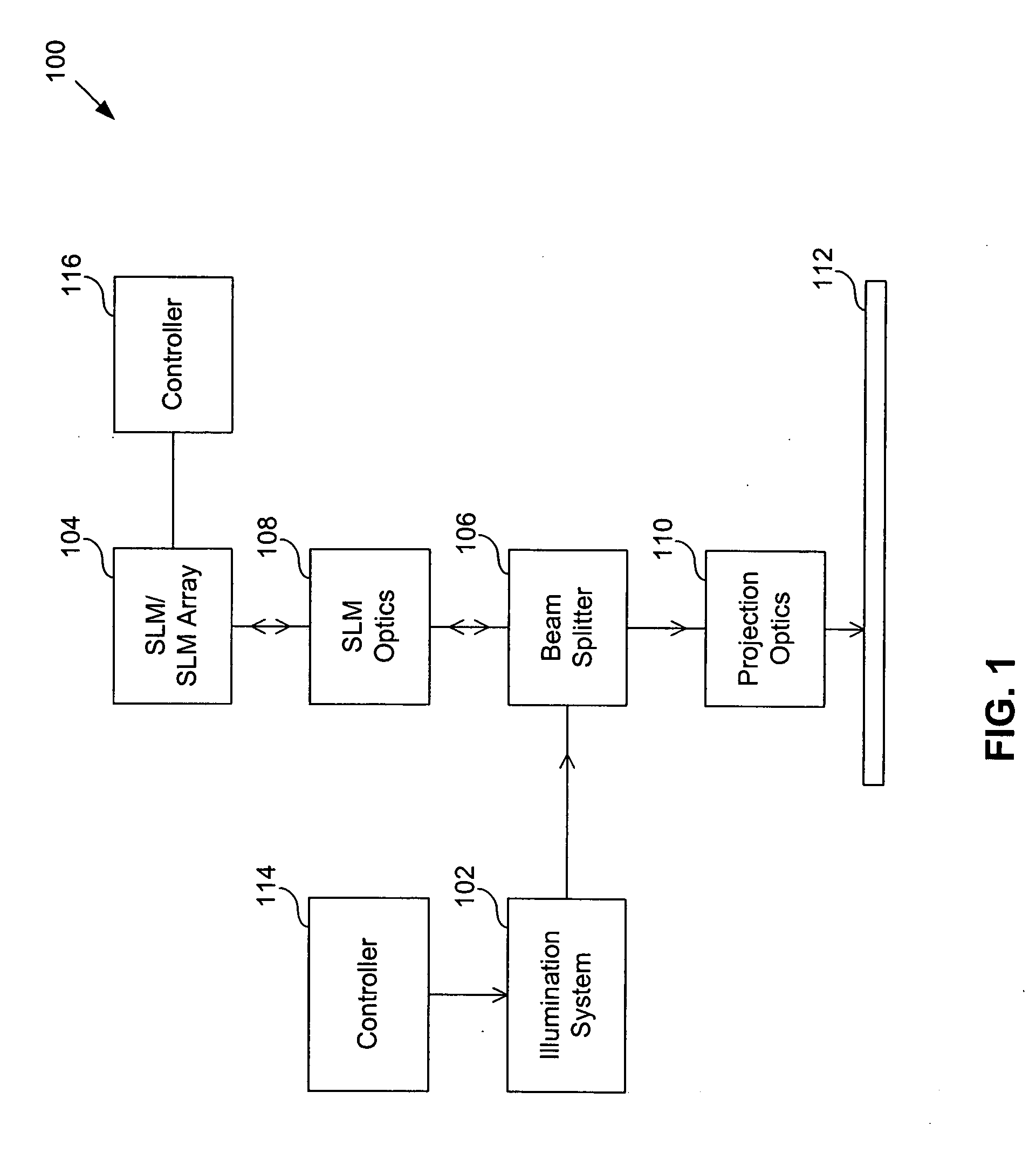
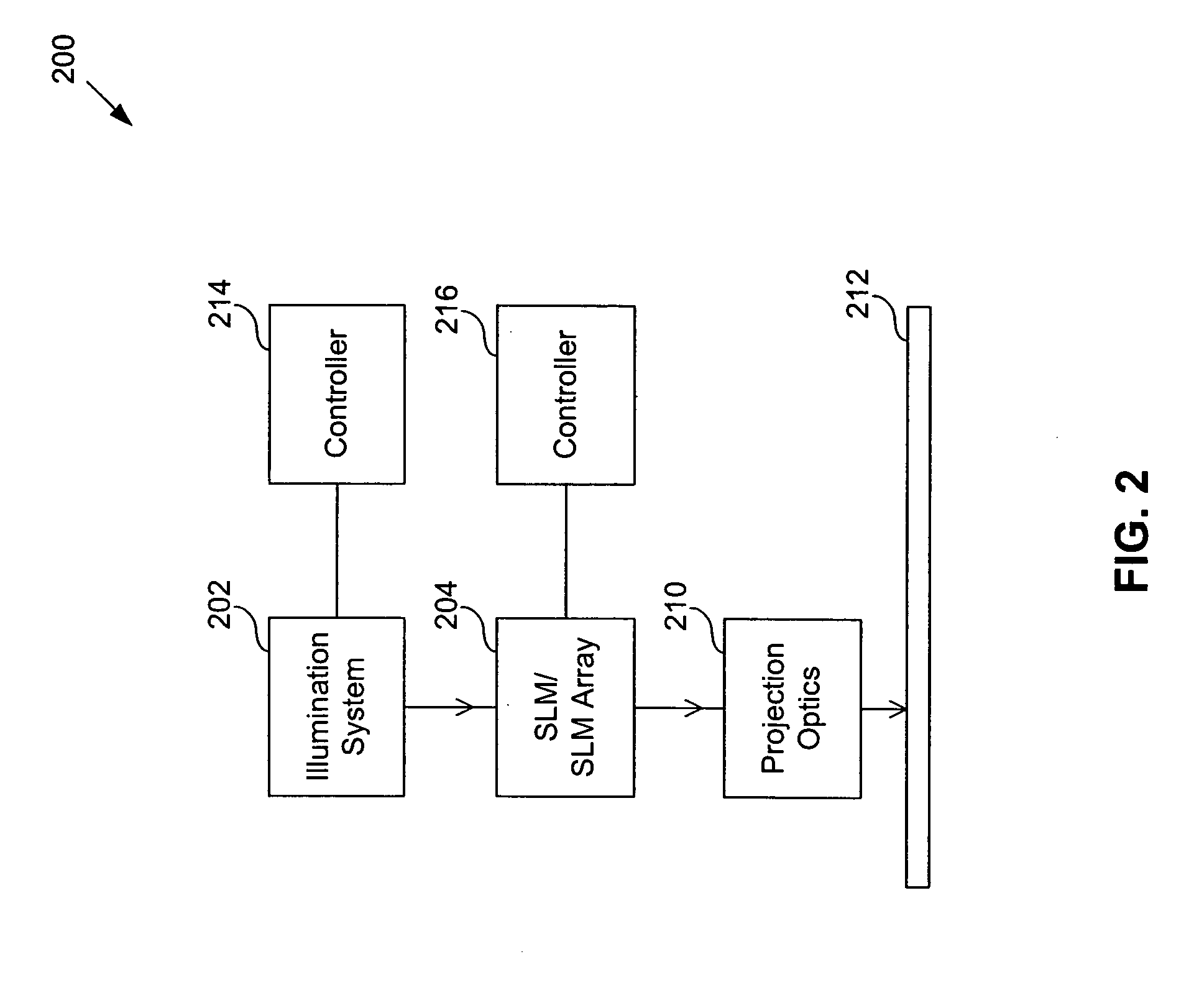
[0031] An embodiment of the present invention utilizes an array of SLMs in a maskless lithography system in order to allow for multiple exposures to the same area on an object surface during each scanning pass. Using the array of SLMs can increase throughput and lower costs compared to conventional maskless systems using only one SLM.

[0032] By integrating multiple SLMs into one mechanical assembly, a field replaceable unit can be made. This unit could integrate mechanical and thermal stability, cooling channels, pur...


PUM

PropertyMeasurementUnit
step sizeaaaaaaaaaa
step sizeaaaaaaaaaa
step sizeaaaaaaaaaa

Abstract

A maskless lithography system that writes patterns on an object. The system can include an illumination system, the object, spatial light modulators (SLMs), and a controller. The SLMs can pattern light from the illumination system before the object receives the light. The SLMs can include a leading set and a trailing set of the SLMs. The SLMs in the leading and trailing sets change based on a scanning direction of the object. The controller can transmit control signals to the SLMs based on at least one of light pulse period information, physical layout information about the SLMs, and scanning speed of the object. The system can also correct for dose non-uniformity using various methods.

Description

CROSS REFERENCE TO RELATED APPLICATIONS [0001] This application is a divisional application of U.S. application Ser. No. 10 / 449,908, filed May 30, 2003, which is incorporated by reference herein in its entirety.BACKGROUND OF THE INVENTION [0002] 1. Field of the Invention [0003] The present invention relates generally to lithography. More particularly, the present invention relates to maskless lithography. [0004] 2. Related Art [0005] Lithography is a process used to create features on the surface of substrates. Such substrates can include those used in the manufacture of flat panel displays (e.g., liquid crystal displays), circuit boards, various integrated circuits, and the like. A frequently used substrate for such applications is a semiconductor wafer or glass substrate. While this description is written in terms of a semiconductor wafer for illustrative purposes, one skilled in the art would recognize that this description also applies to other types of substrates known to those...

Claims


Application Information

Patent Timeline
Patent Type & Authority Applications(United States)
IPC IPC(8): G03F1/00G02F1/13G03F7/20H01L21/027
CPCG03F7/70283G03F7/70291G03F7/70558G03F7/70466G03F7/70358G03F7/2057
Inventor BLEEKER, ARNOCEBUHAR, WENCESLAO A.HINTERSTEINER, JASON D.MCCULLOUGH, ANDREW W.WASSERMAN, SOLOMON
Owner ASML HLDG NV
Why Eureka
Try Eureka