Fiber optic sensing device for measuring a physical parameter

a fiber optic and physical parameter technology, applied in the field of fiber optic sensing technology, can solve the problems of high inaccuracy, difficult to achieve in practice, high cost, etc., and achieve the effect of high accuracy and stability

Active Publication Date: 2005-03-03
PHOTON CONTROL INC
View PDF8 Cites 69 Cited by
  • Summary
  • Abstract
  • Description
  • Claims
  • Application Information

AI Technical Summary

Benefits of technology

to provide such a fiber optic sensing de

Problems solved by technology

Precise mechanical scanning may be done only in a stabilized environment which is costly to achieve and maintain.
However, such way of normalization requires both measuring and calibration conditions to be identical, which is difficult to achieve in practice.
The deviation of the real measuring condition from the calibration condition, which is seen from the fluctuation of the average value in the referred document, leads to the higher inaccuracy because the measuring spectrum could not match with any stored calibrated data.
Although simple, this method also has limited measuring range because the physical parameter can be measured within the fraction of a single fringe.
However, the interpolation error is increased with the smaller number of fringes in the spectrum and, consequently, the accuracy of the determination of the zero-crossing points is reduced.
This complexity increases the response time of the sens

Method used


Image

  • Fiber optic sensing device for measuring a physical parameter
  • Fiber optic sensing device for measuring a physical parameter
  • Fiber optic sensing device for measuring a physical parameter

Examples


Embodiment Construction

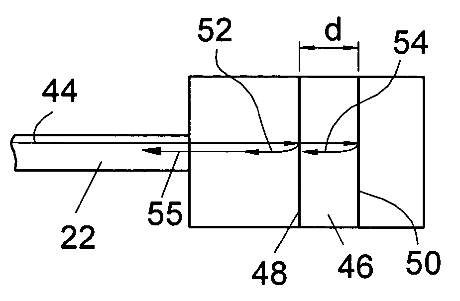
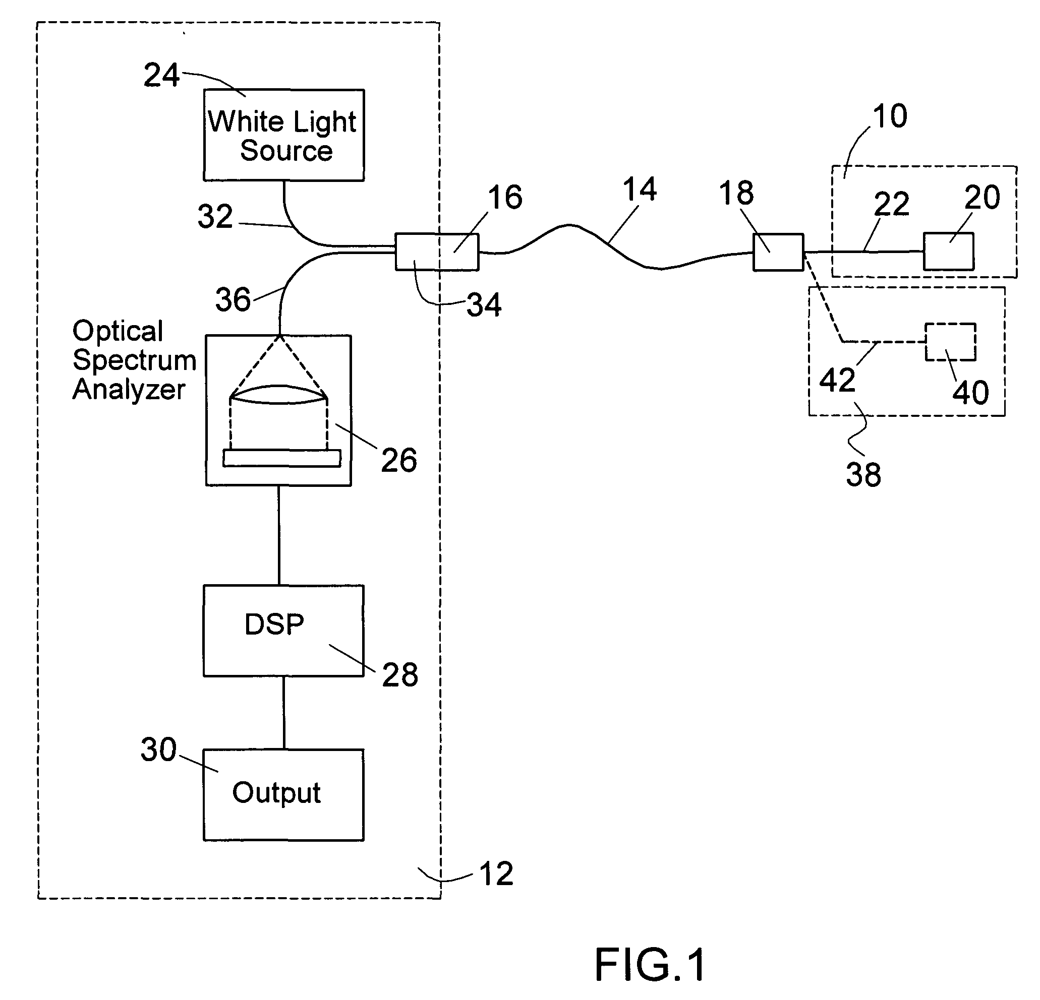
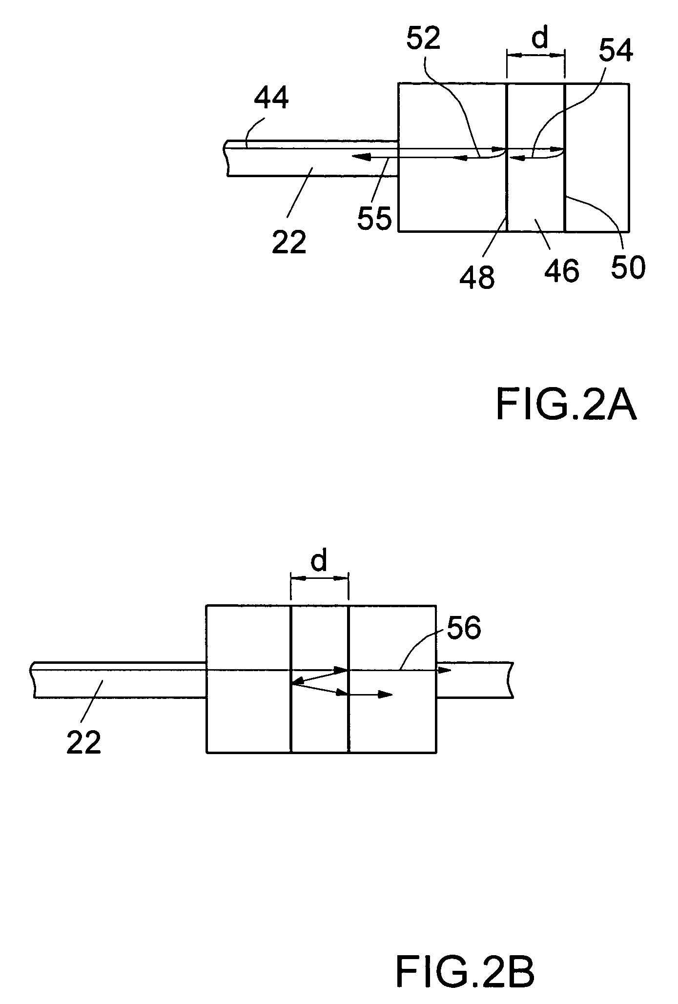
Referring to FIG. 1, the fiber optic sensing device according to the present invention consists of a fiber optic measuring probe (10) connected to an opto-electronic module (12) either directly or through an extension cable (14). The connection is provided by the fiber optic connectors (16) and (18). The measuring fiber optic probe consists of a sensing interferometer (20) coupled with an optical fiber (22) to the connector (18). The sensing interferometer is preferably a Fabry-Perot interferometer, however, the invention may be applied to any kind of fiber optic interferometer which is used to modulate the spectrum of the light.

The opto-electronic module (12) consists of a polychromatic or white light source (24), an optical spectrum analyzer (26), a digital signal processing unit (28) and an output circuit (30). The opto-electronic module includes also a power supply unit (not shown) which delivers the electrical power to all opto-electronic parts above. Preferably, the opto-el...


PUM


Abstract

A fiber optic sensing device uses a Fabry-Perot cavity to sense a physical parameter. The cavity modulates the incident polychromatic light. The modulated light is recorded by an optical spectrometer means. The spectrum is analyzed in a signal processing unit which normalizes the spectrum and determines the phase of the modulated signal. The phase, accumulated over whole range of wavelengths, has been used for identification of the physical parameter using a look-up-table. The cavity, the polychromatic light source and the spectroscope means are connected by fiber optic means.

Description

BACKGROUND OF THE INVENTION The present invention relates to fiber optic sensing technology, and more specifically to a sensor and method using a Fabry-Perot optical interferometer and spectral signal demodulation for measurement of a physical parameter such as a pressure, a temperature, a strain, and a refractive index with a high accuracy and within a large range of physical parameters. Fiber optic interferometric sensors offer a number of advantages over electrical sensors such as inherent immunity to electromagnetic interference, capability of operating in harsh environments and at longer distances, miniature sizes, etc. A fiber optic Fabry-Perot sensor typically consists of a measuring Fabry-Perot probe, a fiber optic extension cable and an opto-electronic module. The measuring Fabry-Perot probe represents a cavity with two partially reflective surfaces. The cavity modulates the spectrum of the incident light depending on cavity spacing and the refractive index of the media i...

Claims


Application Information

Patent Timeline
IPC IPC(8): G01B9/02G01D5/353G01J3/02G01J3/10G01J3/26G01J3/453G01N21/45
CPCG01D5/35303G01J3/02G01J3/0218G01N21/45G01J3/26G01J3/453G01J3/10
Inventor MELNYK, IVAN
Owner PHOTON CONTROL INC
Why Eureka
Try Eureka