Electromagnetic apparatus drive apparatus
a technology of electromagnetic devices and drive units, which is applied in the direction of electrical devices, electric motors with armatures, magnetic bodies, etc., can solve problems such as the sound of electromagnetic devices
- Summary
- Abstract
- Description
- Claims
- Application Information
AI Technical Summary
Benefits of technology
Problems solved by technology
Method used
Image
Examples
first embodiment
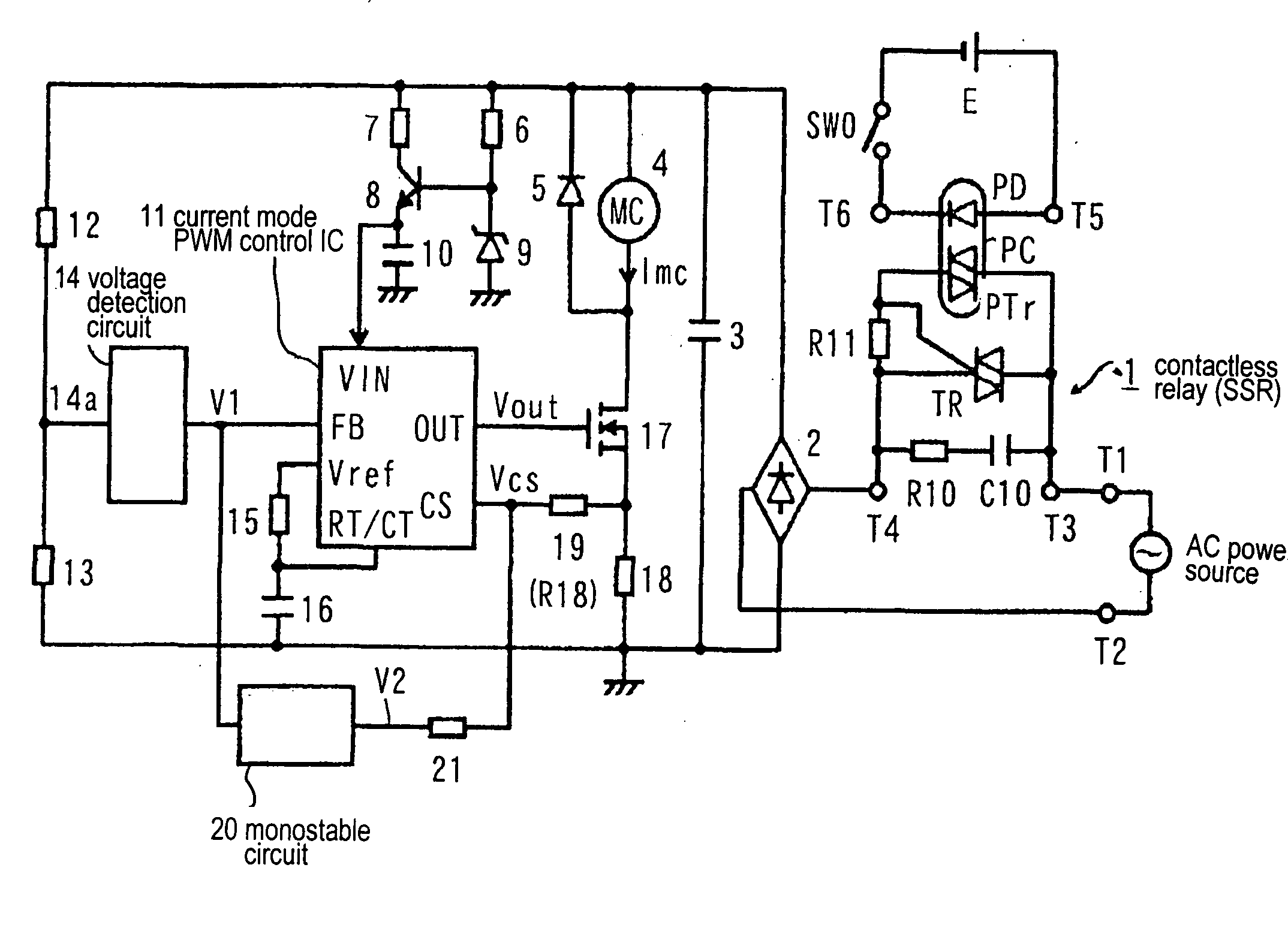
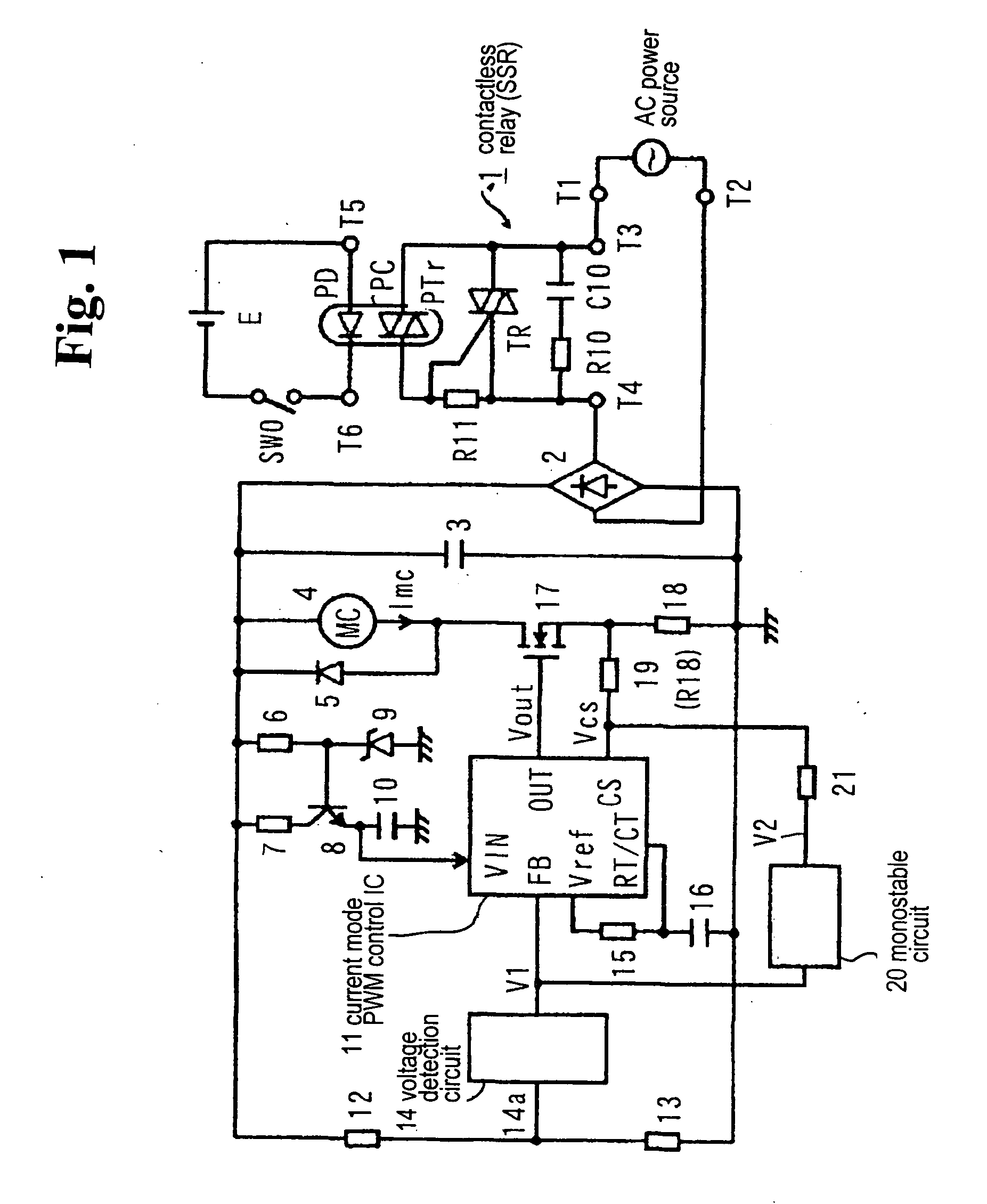
[0053]FIG. 1 shows a circuit diagram of a drive device for an electromagnetic device according to a first embodiment of the present invention. FIG. 6 shows an operational waveform of a main part of the circuit shown in FIG. 1 when the electromagnetic device becomes a hold state. Here, FIG. 1 corresponds to FIG. 4, and FIG. 6 corresponds to FIG. 9.
[0054] The circuit diagram shown in FIG. 1, in addition to the components shown in FIG. 4, comprises an mono-stable circuit 20 and a resistor 21 connected between an output terminal of the mono-stable circuit 20 and a current detection terminal CS of a current mode PWM control IC 11. As shown in FIG. 6, the mono-stable circuit 20 is triggered when a voltage V1 of an H level outputted by a voltage detection circuit 14 decreases within a non-conductive interval t1 centered around a 0 cross point with the AC powder source voltage. A voltage V2 of the H level is outputted within a period t2 comprising a plurality of periods T of a latch set pu...
second embodiment
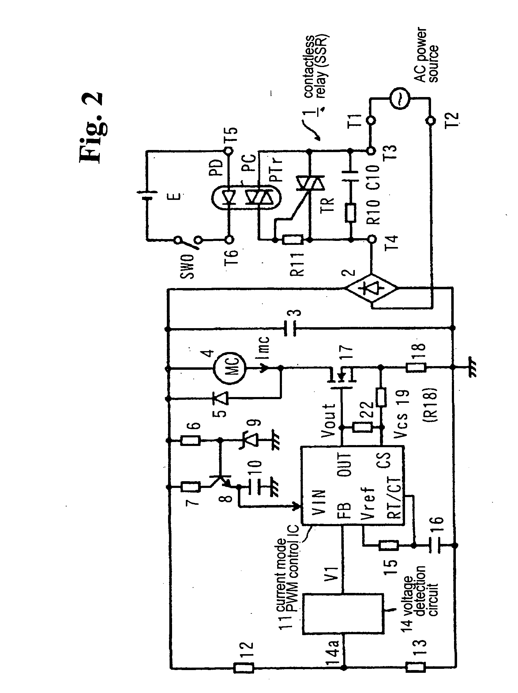
[0058]FIG. 2 shows a circuit diagram of a drive device for an electromagnetic device according to a second embodiment of the present invention. FIG. 7 shows an operational waveform of a main part of the circuit shown in FIG. 2 when the electromagnetic device becomes a hold state. Here, FIG. 2 corresponds to FIG. 4, and FIG. 7 corresponds to FIG. 9.
[0059] The circuit diagram shown in FIG. 2, in addition to the components shown in FIG. 4, comprises a resistor 22 connected between the PWM pulse output terminal OUT of the current mode PWM control IC 11 and the current detection terminal CS. In the circuit shown in FIG. 2, each time the PWM pulse Vout of the H level is outputted, the voltage of the PWM pulse Vout is divided by the resistors 22 and 19 and current detection resistor 18. Accordingly, in this case, the superimposed voltage of the divided voltage component of the PWM pulse Vout, i.e. the voltage applied to the resistor 19, and the voltage (Imc×R18) of the current detection r...
third embodiment
[0061]FIG. 3 shows a circuit diagram of a drive device for an electromagnetic device according to a third embodiment of the present invention. FIG. 8 shows an operational waveform of a main part of the circuit diagram shown in FIG. 3 when the electromagnetic device becomes a hold state. Here, FIG. 3 corresponds to FIG. 1, and FIG. 8 corresponds to FIG. 6.
[0062] In the circuit diagram shown in FIG. 3, in addition to the components shown in FIG. 1, an AND circuit 23 having one input terminal connected to the output of the mono-stable circuit 20 is inserted between the mono-stable circuit 20 and the resistor 21, and the other input terminal of the AND circuit 23 is connected to the PWM pulse output terminal OUT of the current mode PWM control IC 11. In the circuit diagram shown in FIG. 3, as shown in FIG. 8, within the interval t2 in which the output V2 of the mono-stable circuit 20 becomes the H level, the interval following the non-conductive interval t1, i.e. the output voltage V3 ...
PUM
| Property | Measurement | Unit |
|---|---|---|
| voltage | aaaaa | aaaaa |
| voltage Vref | aaaaa | aaaaa |
| voltage | aaaaa | aaaaa |
Abstract
Description
Claims
Application Information
 - R&D
- Intellectual Property
- Life Sciences
- Materials
- Tech Scout
- Unparalleled Data Quality
- Higher Quality Content
- 60% Fewer Hallucinations
Browse by: Latest US Patents, China's latest patents, Technical Efficacy Thesaurus, Application Domain, Technology Topic, Popular Technical Reports.
© 2025 PatSnap. All rights reserved.Legal|Privacy policy|Modern Slavery Act Transparency Statement|Sitemap|About US| Contact US: help@patsnap.com


