Dc/ac conversion device and ac power supply method

a conversion device and ac power supply technology, applied in the direction of electric variable regulation, process and machine control, instruments, etc., can solve the problems of low power inversion efficiency, inability to maintain a constant output voltage, and difficulty in miniaturizing such inverters, so as to reduce the effect of switching loss

Active Publication Date: 2005-03-03
ROHM CO LTD
View PDF11 Cites 35 Cited by
  • Summary
  • Abstract
  • Description
  • Claims
  • Application Information

AI Technical Summary

Benefits of technology

[0084] An inverter of the invention generates an ac voltage from a dc power supply for driving a load connected to a secondary winding of a transformer. The inverter is equipped with a full-bridge or a half-bridge type semiconductor switch circuit formed in the primary winding of the transformer. Transformer has a secondary winding for connection with a load. The switch circuit is adapted to feed back the current flowing in the load to carry out PWM control of the respective switches of the circuit, thereby enabling fine regulation of the electric power supplied to the load.
[0085] The invention also enables sophisticated control including zero-current switching, penetrating current prevention, and reduction of switching loss by employing adequate switching logics to the control of a multiplicity of semiconductor switches using pulse-width modulation (PWM) signals.

Problems solved by technology

However, a Royer circuit is basically a constant-voltage inverter, which cannot maintain a constant output voltage if the input voltage thereto and / or the load current thereof varies.
For this reason, besides the inverter utilizing a Royer circuit has low power inversion efficiency, it is difficult to miniaturize such inverter.
Conventional inverters utilizing Royer circuit are not only difficult to be miniaturized but also disadvantageous in that their conversion efficiencies are low.
Hence, the inverter has a structural limitation that the four semiconductor switches must be of the same conduction type.
Moreover, the prior art inverters have difficulty to regulate the power supplied to the load over a wide range, especially for the purpose of dimmer control.

Method used


Image

  • Dc/ac conversion device and ac power supply method
  • Dc/ac conversion device and ac power supply method
  • Dc/ac conversion device and ac power supply method

Examples


first embodiment

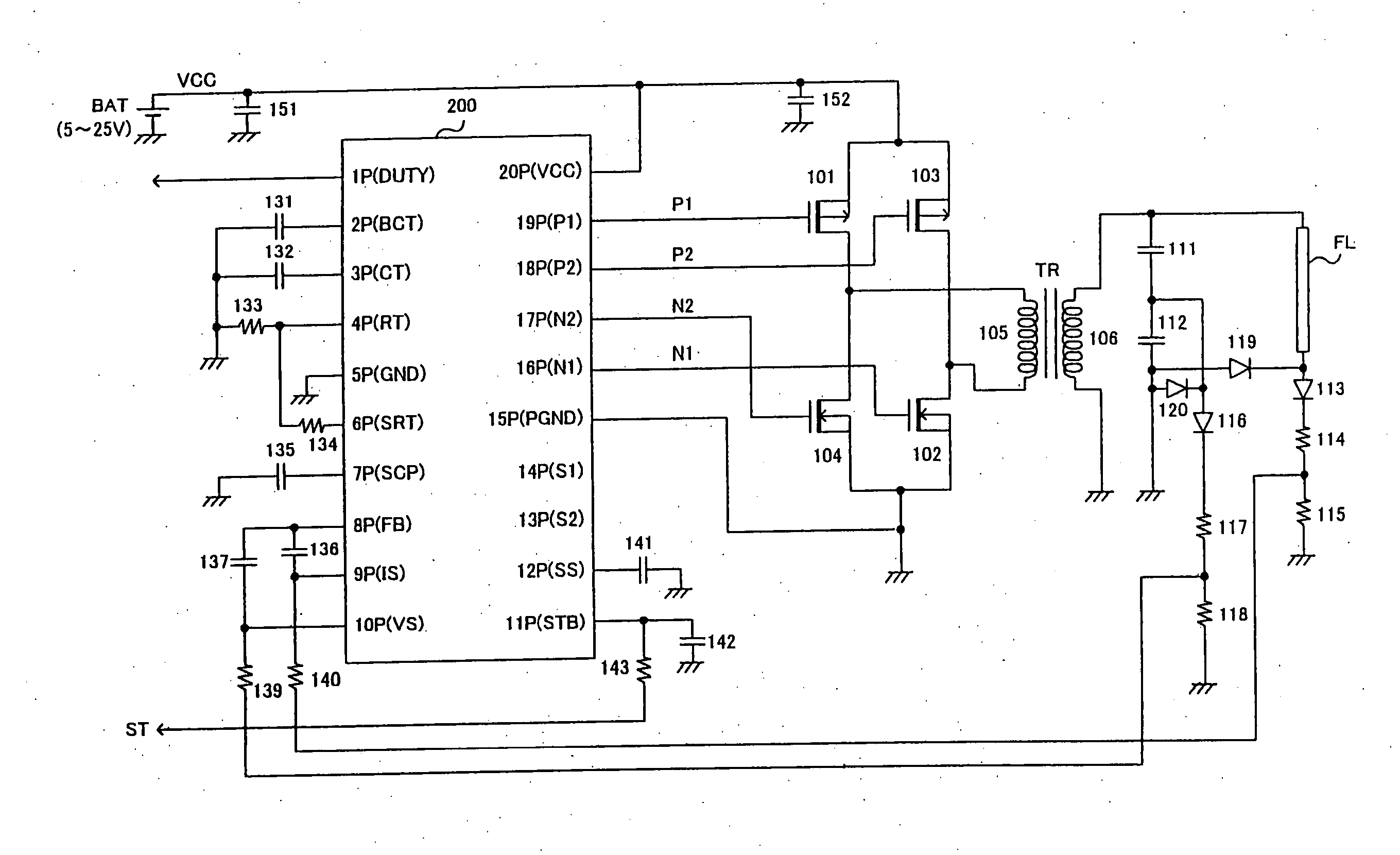
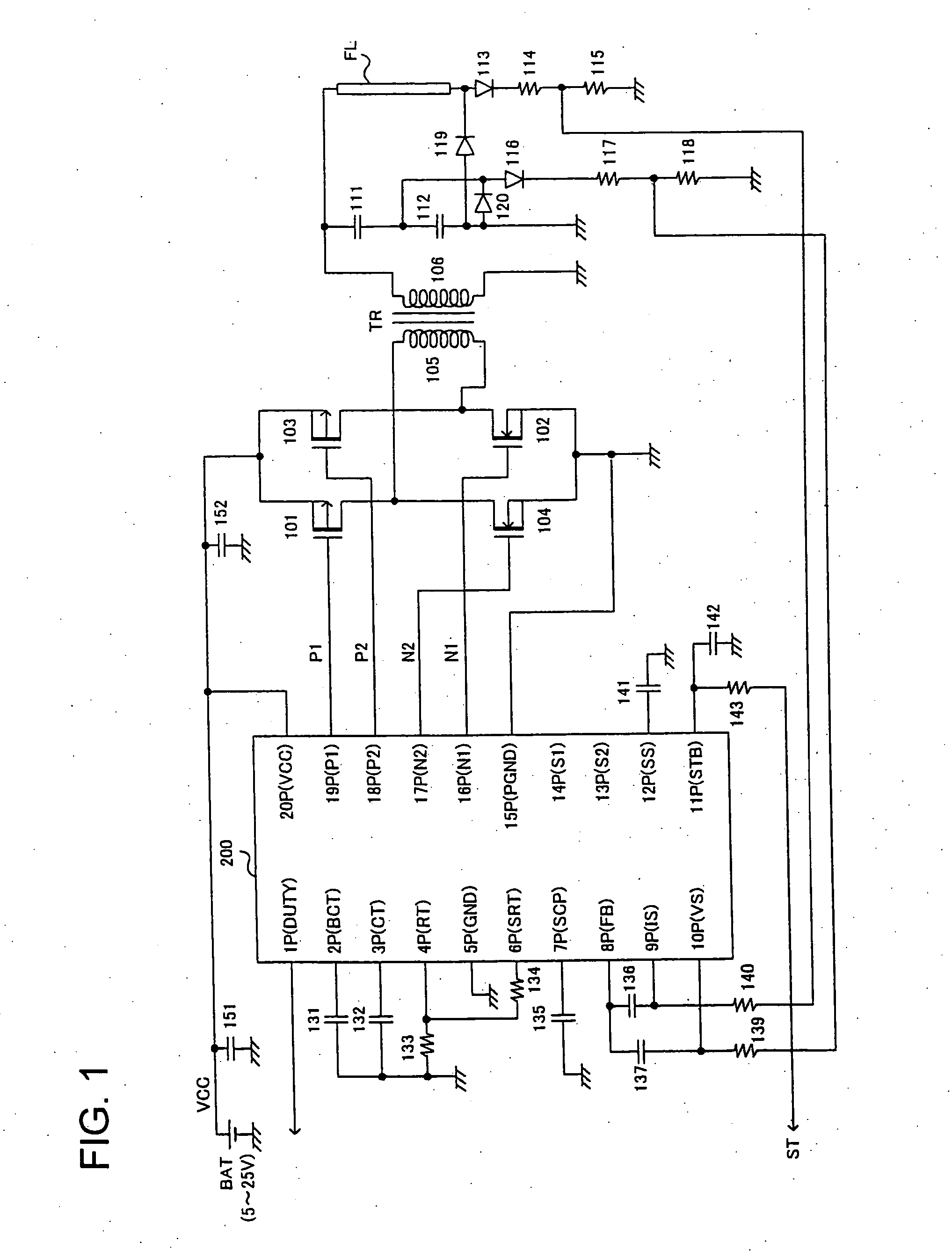
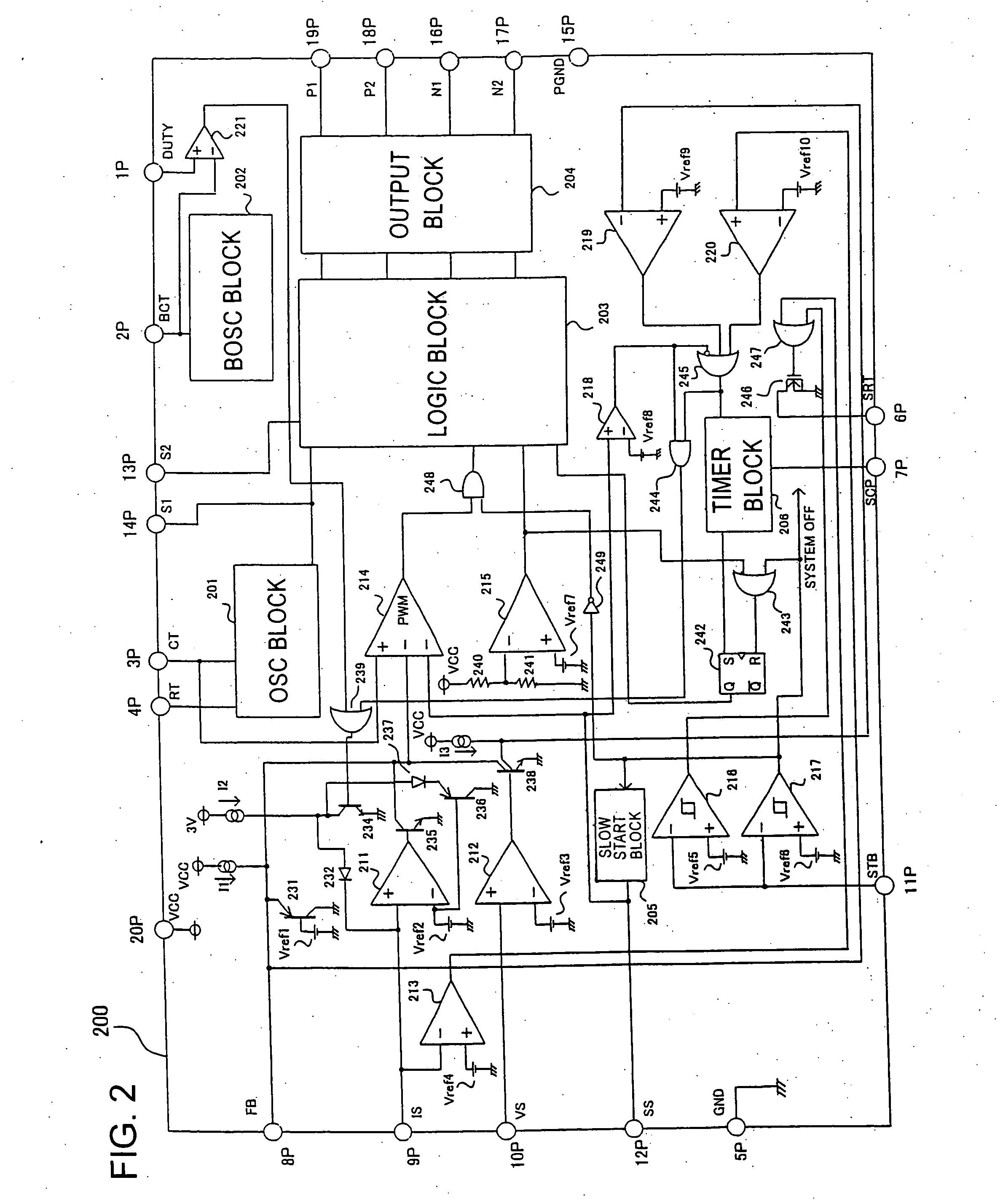
[0095] Referring to FIG. 1, there is shown an over-all arrangement of a first inverter according to the invention that utilizes an insulated transformer and a full-bridge switch circuit to carry out PWM control. FIG. 2 illustrates the internal structure of a controller IC (i.e. IC for controlling inverter) for use in the inverter of FIG. 1. FIG. 3 is a timing diagram for a FIG. 4 is a timing diagram illustrating further details of a part of the timing diagram shown in FIG. 3. FIG. 5 illustrates the operating conditions of the full-bridge at different stages the each timing.

[0096] As shown in FIG. 1, a first switch in the form of a P-type MOSFET (hereinafter referred to as PMOS) 101 and a second switch in the form of an N-type MOSFET (hereinafter referred to as NMOS) 102 constitute a current path in a first direction to the primary winding 105 of a transformer TR. A third switch in the form of a PMOS 103 and a fourth switch in the form of NMOS 104 constitutes a second current path i...

second embodiment

[0167] The current in the first direction will become zero when the energy stored in the transformer TR1 is exhausted. Thus, a condition of zero current is also established in the second embodiment before the direction of the current through the primary winding 308 is switched.

[0168] Such zero-current condition prior to the switching of the current direction can be attained by optimizing the pulse width in the PWM control in accordance with electric properties of the transformer TR1, resonance capacitors 311, 312, 315 and 316, cold cathode fluorescent lights FL11 and FL12, etc. involved.

[0169] In the period iii when the gate drive signal P1 has gone to L level, a current flows in the second direction from the power supply BAT to the primary winding 308 via the PMOS 303 and the second capacitor 304.

[0170] In period iv when the gate drive signal P1 is H level, a simultaneous OFF period Toff is established in which both the PMOS 303 and NMOS 302 are turned off, thereby preventing a p...


PUM


Abstract

A dc-ac converter capable of supplying a finely regulated ac drive voltage to a load is provided. For this purpose, the converter includes, in a primary winding of a transformer, a full-bridge or half-bridge type semiconductor switch circuit whose switches can be controlled by pulse-width modulation. Transformer has a secondary winding for connection with a load. Based on PWM signals and by use of adequate switching logics for controlling multiple semiconductor switches, sophisticated control including zero-current switching and penetrating current prevention can be effected. Moreover, by means of regulated burst control of the ratio of on-duty period to off-duty period together with pulse-width modulation control, power supplied to the load can be regulated over a wide range beyond the limits of control obtained by the pulse-width modulation.

Description

TECHNICAL FIELD [0001] This invention relates to a dc-ac converter (hereinafter referred to as inverter) for generating ac power to drive a load from a dc power supply unit such as a power supply adapter of an electric appliance and a battery. The invention also relates to a method of supplying ac power to a load. BACKGROUND ART [0002] A cold cathode fluorescent light (CCFL) has been increasingly used as a back light source of a liquid crystal display monitor of a notebook PC and of a liquid crystal display (LCD) for use with, for example, a TV set. Such CCFL has substantially the same high efficiency and life as a usual hot cathode fluorescent light, without using a filament of the hot cathode fluorescent light. [0003] In order to start up and operate the CCFL, a high ac voltage is required. For example, a startup voltage of about 1000 V and an operating voltage of about 600 V are required. These high ac voltages are generated from a dc power supply unit of, for example, a notebook...

Claims


Application Information

Patent Timeline
Patent Type & Authority Applications(United States)
IPC IPC(8): H02M7/538H02M3/28H05B41/282H05B41/392
CPCH02M7/53803H02M7/53871H02M2001/008Y02B20/186H05B41/2824H05B41/2828H05B41/3927H05B41/245Y02B20/00H02M1/008H02M7/5395H02M7/537
Inventor FUKUMOTO, KENICHI
Owner ROHM CO LTD
Why Eureka
Try Eureka