
Communication relay method and device

a communication relay and relay technology, applied in the field of communication schemes, can solve the problems of slowing down of communication speed or delay in response, affecting the quality of communication, so as to prevent deterioration of priority communication quality and change flexibly

Inactive Publication Date: 2005-03-03
FUJITSU LTD
View PDF16 Cites 58 Cited by
  • Summary
  • Abstract
  • Description
  • Claims
  • Application Information

AI Technical Summary

Benefits of technology

Using this communication relay method, communications that are registered in the priority table are relayed with higher priority. Which communications are handled with higher priority depends on which communications are registered in the priority table. The registration of communications in the priority table is performed in accordance with a request of the communication managing device. Let us consider, for example, the case that the communication managing device is a SIP server managing VoIP telephone communication. In this case, of all the communications performed by the wireless terminal, only VoIP communications are registered by the SIP server in the priority table. As a result, when the wireless terminal is performing a plurality of communications, only the VoIP communications among those are relayed with higher priority. That is to say, the priority control of which communications are prioritized is not carried out within the wireless system including the relay device and the wireless terminals, but substantially by a communication managing device that is arranged outside. Thus, there is the advantage that the method of the priority control can be flexibly changed, in accordance with the circumstances.
As the wireless terminal moves, the communication identifier listed in the priority table of the relay device of the original location is sent to the priority table of the relay device of the destination location. A new communication identifier is registered in the guest entries of the priority table of the destination location, and the communication identifier is deleted from the entries for existing terminals in the priority table of the original location. The priority tables are updated as the wireless terminal moves, so that the bandwidth for prioritized communication in the relay devices can be used advantageously.
In accordance with the present invention, which communications are prioritized can be changed flexibly according to needs. Moreover, it possible to prevent a deterioration of the quality of prioritized communication due to conflicts among prioritized communications.

Problems solved by technology

Consequently, it is not possible that a plurality of wireless terminals simultaneously perform communication completely independently from one another.
For example, effects such as a slow-down of the communication speed or delays in the response may occur.
In this situation, when a communication necessitating a lot of communication bandwidth is started by another wireless terminal, the audio data being communicated may arrive at a certain delay.
As a result, the audio of the communication partner may be reproduced at a delay, or a cut-off noise or the like may occur when the reproduction of the audio data occurs too late.
However, currently available wireless LAN systems do not support the PCF mode, and at present, priority control in wireless LANs is not performed by a standardized method.
However, as the number of wireless terminals operating in this manner is increased, there is the danger that the probability for contention rises, and the communication quality decreases.
However, in general there are only few devices that utilize this information, and there is the risk that difficulties arise when mixing different services.
There is furthermore the possibility that the entire network is put at risk when there are terminals with which an application operating on wireless terminals and wired terminals is intentionally set to incorrect settings in order to ensure a high priority degree.
However, the algorithm for referencing the header and distribution to the queues is fixed, so that it is difficult to dynamically change the method of the priority control.
In this case, there is the possibility that it is not possible to preserve the communication quality of prioritized communication, even when performing priority control, due to the influence that prioritized communications have on one another on a crowded network.
As for problem (4), there is a limitation on the bandwidth that can be used by wireless terminals performing prioritized communication, so that one problem that arises is how conflicts among prioritized communications can be solved.
Moreover, in wireless LANs, when the state of the wireless communication between the wireless terminals and the wireless relay station becomes poor and errors become frequent, then a function is activated that reduces the connection speed to maintain the communication quality.

Method used


Image

  • Communication relay method and device
  • Communication relay method and device
  • Communication relay method and device

Examples


first embodiment

(1) Configuration

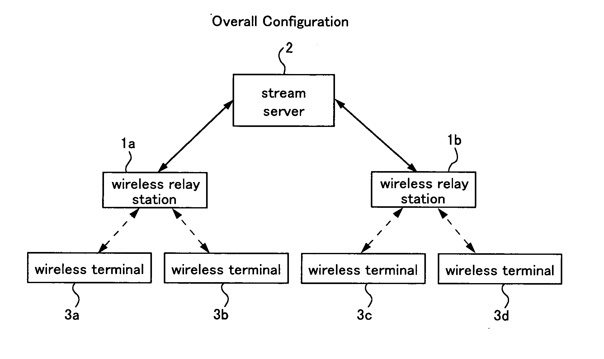
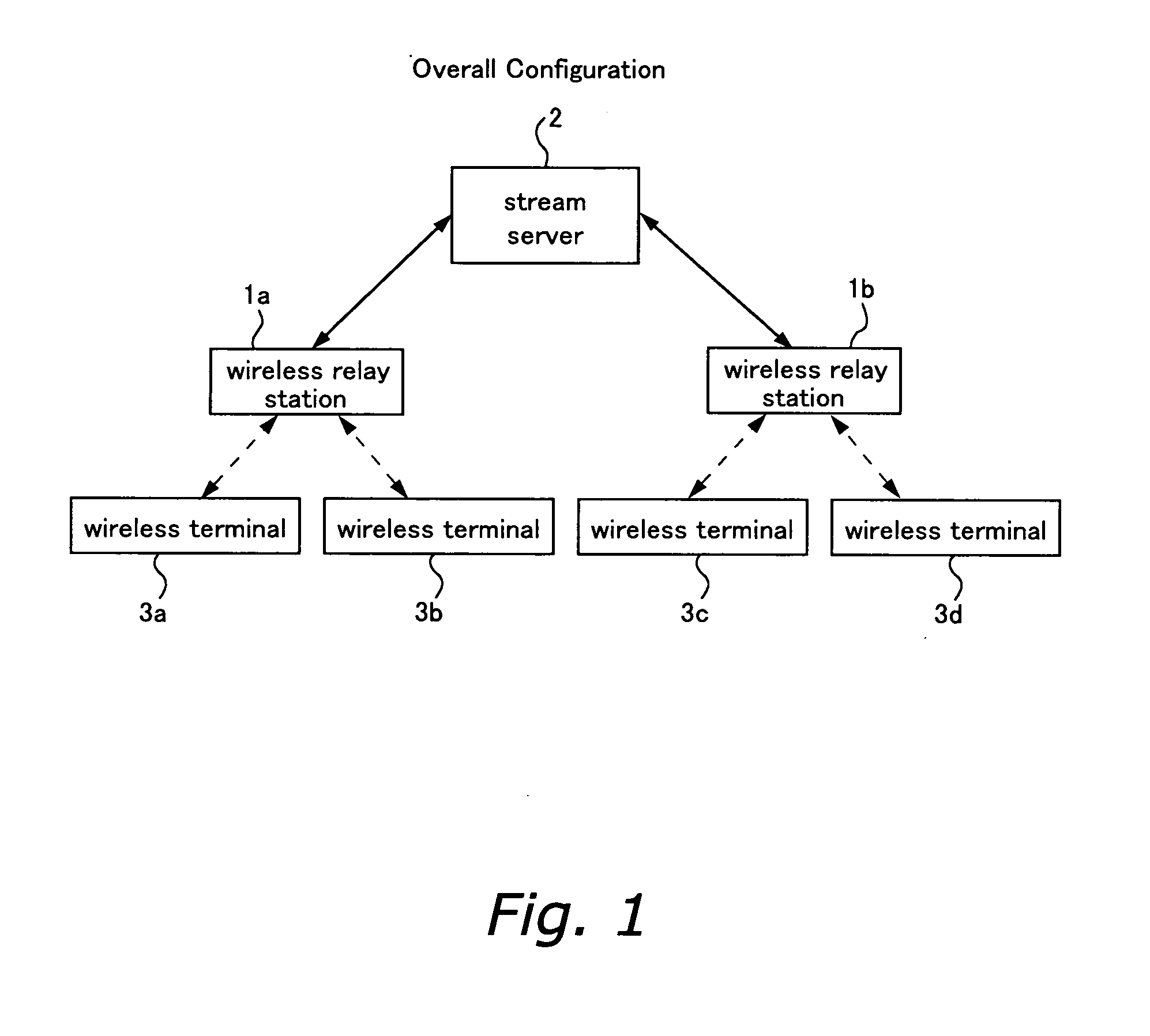
FIG. 1 shows the overall configuration of a wireless communication system according to a first embodiment. The wireless communication system includes at least one wireless relay station 1a, 1b, a stream server 2, and a plurality of wireless terminals 3a to 3d. The functional configurations of the wireless relay stations and the wireless terminals are the same, and unless it is necessary to differentiate between them, they are referred to without the letters a, b, etc.

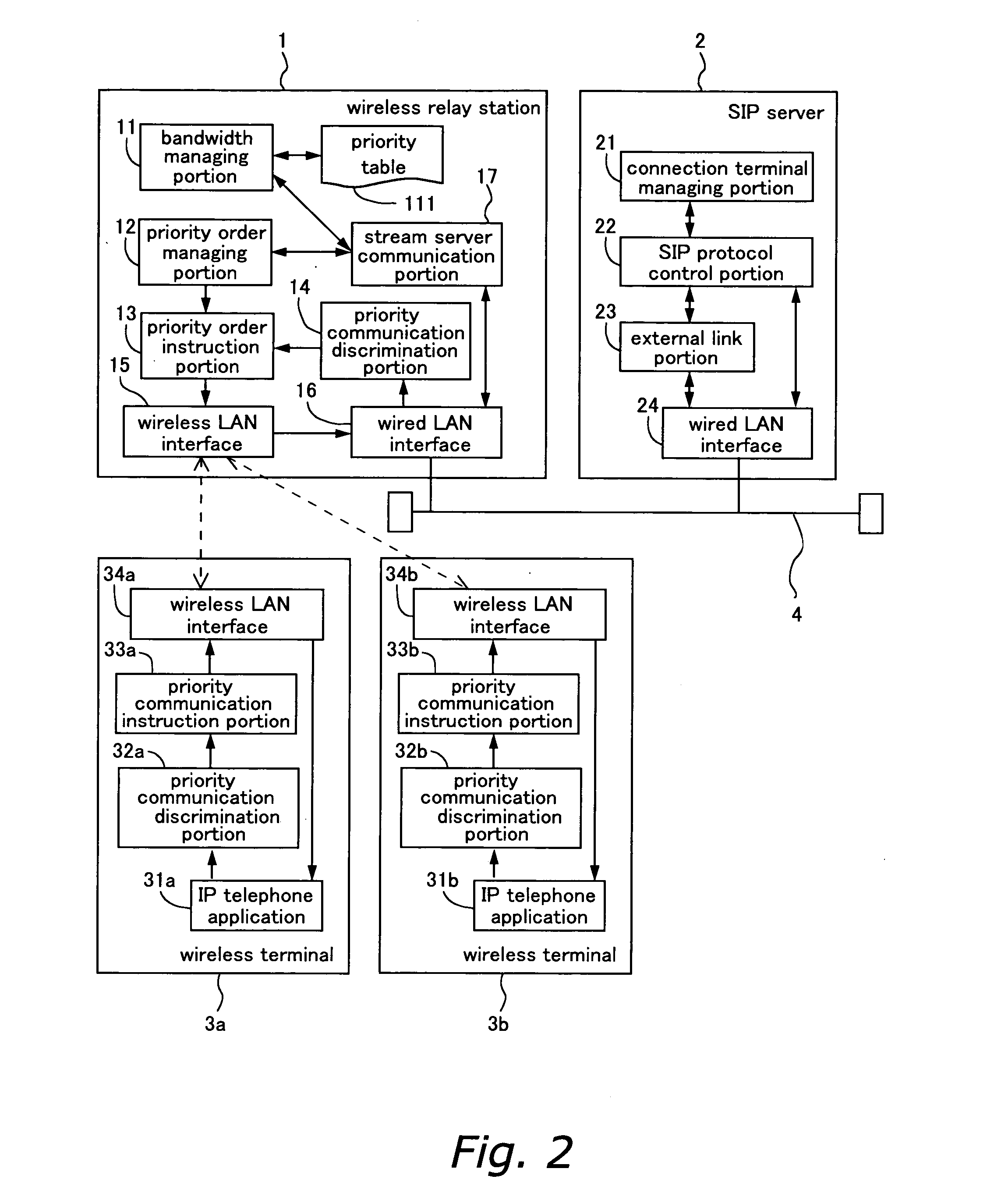
The wireless terminals 3 can be connected via a wireless LAN to any of the wireless relay stations 1. The wireless stations 1 are connected to one another by a wired LAN 4 (see FIG. 2). Furthermore, the wireless relay stations 1 are connected via a wired LAN 4 to a stream server 2.

The stream server 2 handles all or a portion of the wireless communication of the wireless terminals 3, and uses communication identifiers to discriminate the various communications to be handled. An example of the strea...

second embodiment

In the first embodiment, an upper limit is provided for the number of prioritized communications registered in the priority table 111, thus restricting the registrations in the priority table 111. Another method is to judge whether resources for prioritized communication are available based on the bandwidth that the wireless terminals 3 consume by wireless communication (referred to as “consumption bandwidth” in the following).

FIG. 5 shows the functional configuration of a wireless relay station 1, a SIP server 2 and wireless terminals 3 according to a second embodiment. Elements having the same function as in the first embodiment are denoted by the same reference numerals. Differences to the first embodiment are the fact that a signal administration table 112 is provided, as well as the information stored in the priority table 113.

FIG. 6 is a schematic illustration of the signal administration table 112. Registered in the signal administration table 112 are communication identif...

third embodiment

In the first and the second embodiment, it is possible to combine the priority table 111 or the priority table 113 and the signal administration table 112 to one table.

FIG. 8 shows an administration table in which the priority table 113 and the signal administration table 112 of the second embodiment have been combined. It is possible to perform the same processing as described above, when using the administration table shown in FIG. 8 instead of the priority table 111 shown in FIG. 1, or instead of the combination of the priority table 113 and the signal administration table 112 shown in FIG. 6. The communication bandwidth necessary for the signaling communication can be calculated based on the number of wireless terminals or the connection process frequency.


PUM


Abstract

The wireless communication system configured in this manner performs priority control of communication as follows: (a) A wireless relay station stores a priority table in which, from among the communications handled by the stream server, the identifiers of those communications that are relayed with higher priority are registered. (b) The wireless relay device relays communications specified by the communication identifiers registered in the priority table with higher priority than other communications. (c) The stream server receives communication start requests from any of the wireless terminals and sends to the wireless relay station communication identifiers specifying the communications that are about to be started, and requests registration in the priority table. (d) The wireless relay station registers the communication identifiers whose registration has been requested in the priority table, to an extent that a proportion S / U of a sum S of consumption bandwidths of the communications specified by communication identifiers registered in the priority table to the available bandwidth U of the wireless network does not exceed a predetermined upper limit. Thus, flexible priority control is performed, and the quality of prioritized communication can be ensured.

Description

FIELD OF THE INVENTION The present invention relates to communication schemes in which a plurality of users belonging to the same communication area share a limited communication bandwidth, as in a wireless LAN (local area network). More specifically, the present invention relates to such communication schemes, wherein degrees of priority are assigned to each of the communications of the plurality of users, and the quality of communications with a high degree of priority is ensured. BACKGROUND ART In wireless data communication systems, such as wireless LANs, the same data reaches wireless terminals that are present within an area receiving the radio waves from a wireless relay station. That is to say, communication data between the wireless relay station and a given wireless terminal is simultaneously communicated to the other terminals as well. Consequently, it is not possible that a plurality of wireless terminals simultaneously perform communication completely independently fr...

Claims


Application Information

Patent Timeline
Patent Type & Authority Applications(United States)
IPC IPC(8): H04L12/801H04B7/15H04L12/70H04L12/851H04L12/911
CPCH04B7/155
Inventor MATSUKURA, RYUICHIYAMAUCHI, HITOSHI
Owner FUJITSU LTD
Learn More