

Polymer electrolyte fuel cell system and operation method thereof
a fuel cell and polymer electrolyte technology, applied in the direction of fuel cells, water management in fuel cells, electrochemical generators, etc., can solve the problems of short life and fatal drawbacks of over conventional operation methods, and achieve efficient heating of the total enthalpy heat exchanger, effective utilization of fuel gas, and efficient heat exchange
- Summary
- Abstract
- Description
- Claims
- Application Information
AI Technical Summary
Benefits of technology
Problems solved by technology
Method used
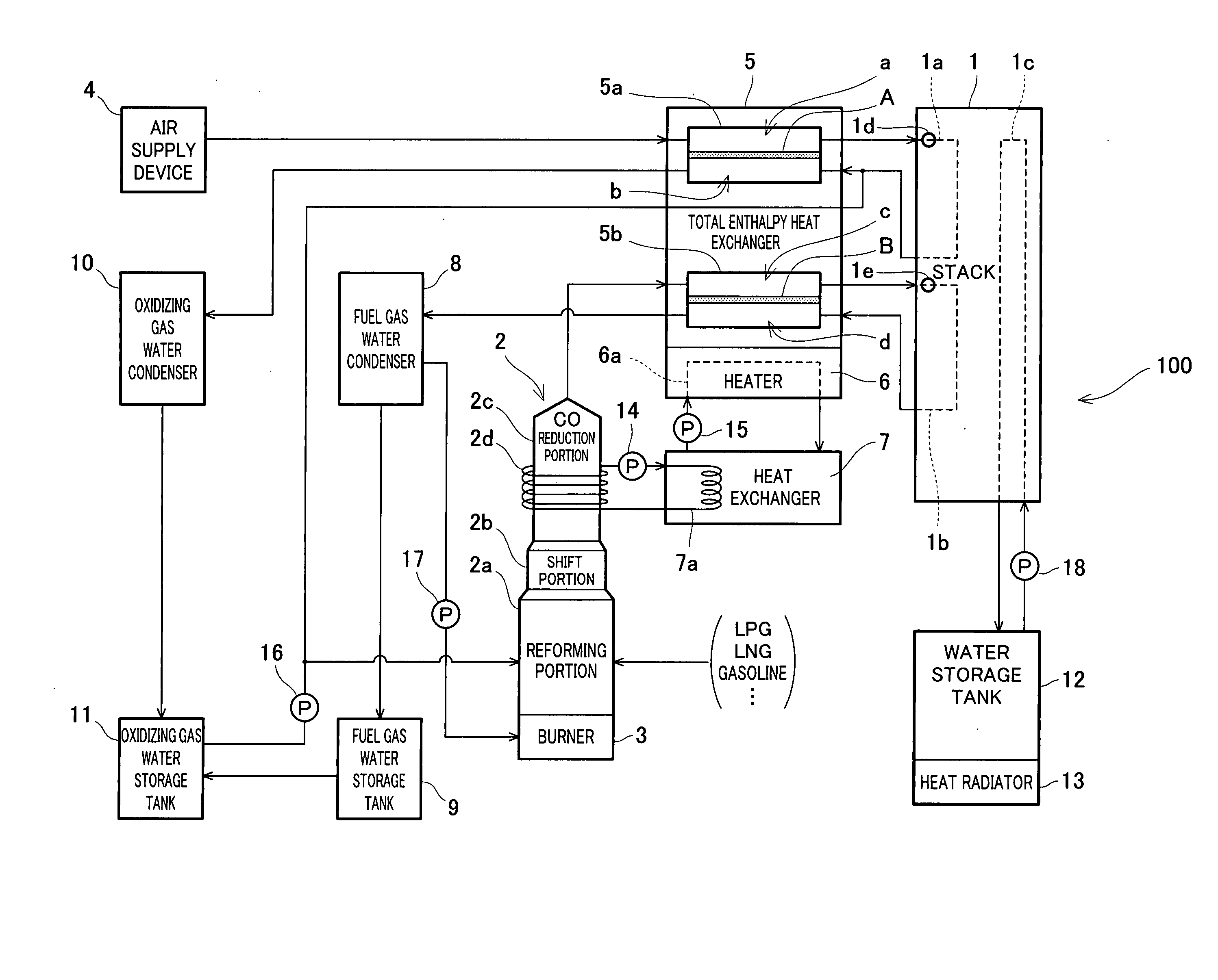
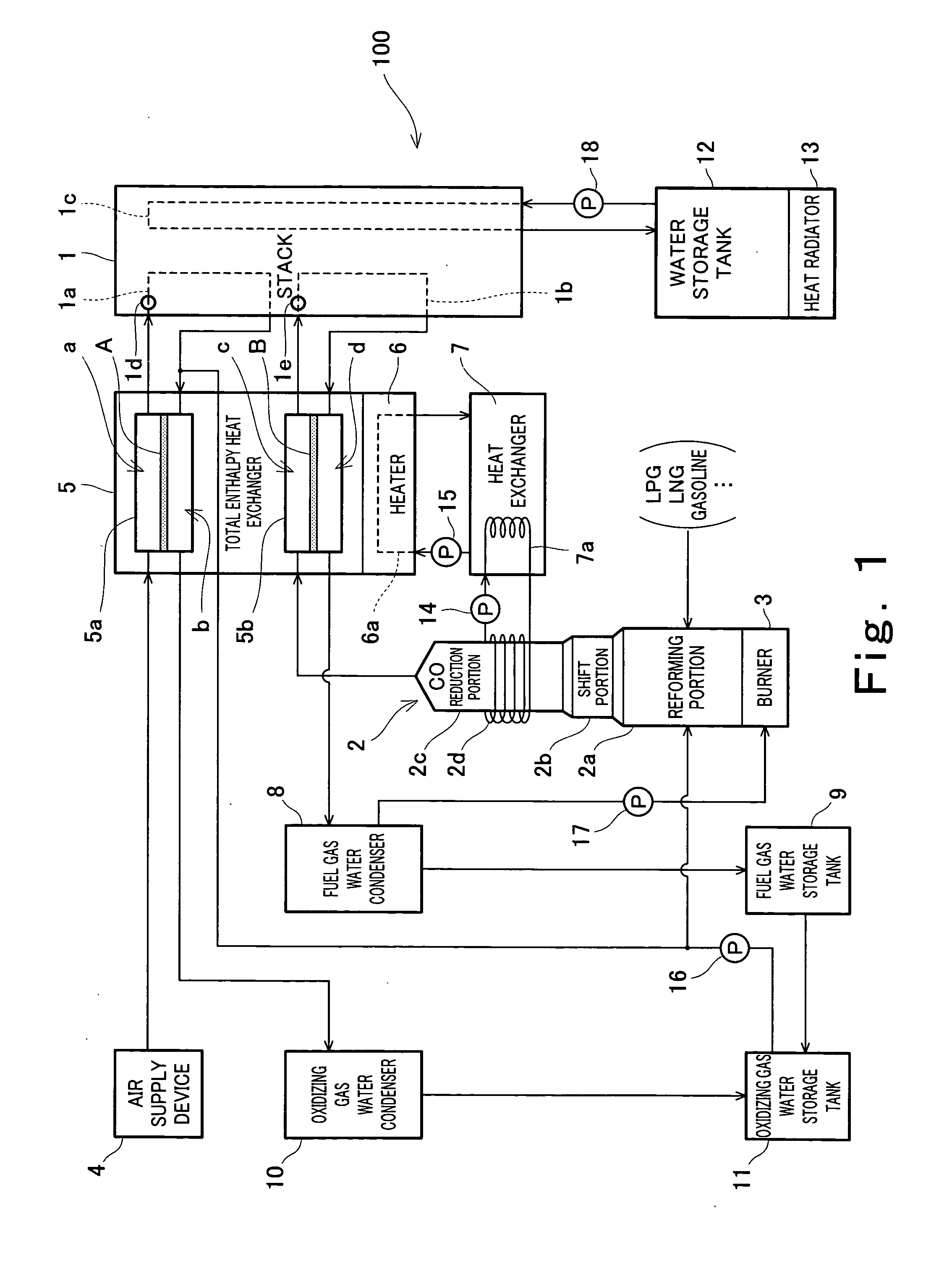
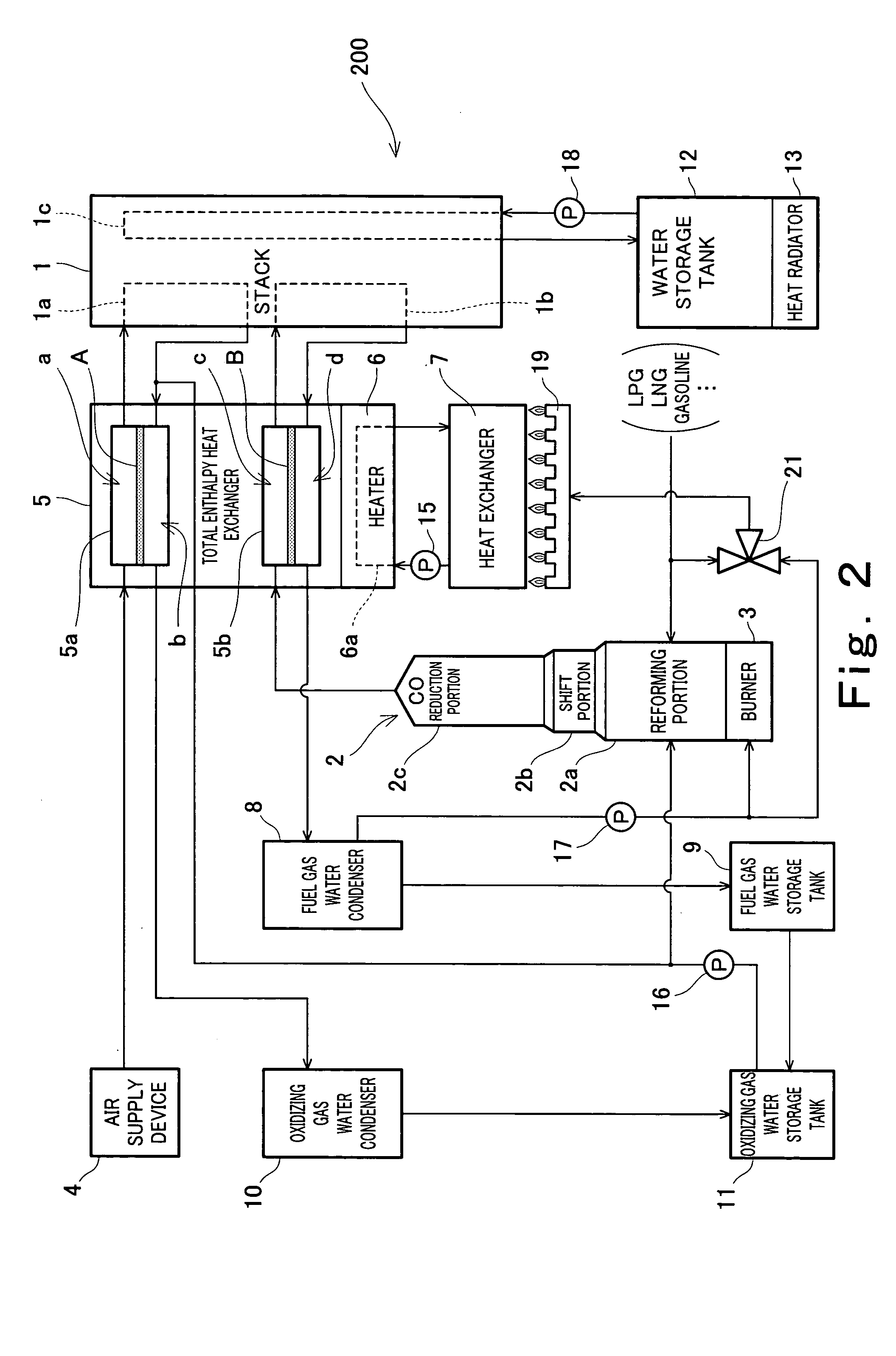
Image

Examples
example 1
[0120] Using a stack formed by stacking 30 cells, a test was conducted to research effects of the amount of water contained in the fuel gas and the oxidizing gas on a cell life characteristic.
[0121]FIG. 8 is a graph showing a cell life characteristic under the condition in which the stack is operated at a current density of 0.7 A / cm2. FIG. 9 is a graph showing a cell life characteristic under the condition in which the stack is operated at a current density of 0.2 A / cm2. In the graphs in FIGS. 8 and 9, abscissa axis represents operation time (Hr) and ordinate axis represents average value (mV) of a cell voltage of each cell. In this test, in operation of the stack, a fuel utilization ratio (Uf) was set to 75%, an air utilization ratio (Uo) was set to 40%, and the operating temperature of the predetermined portion in the stack was set to 70° C.
[0122] The cell life characteristic in FIG. 8 is obtained under the following setting, regarding the dew point (Tda) of the fuel gas and the...
example 2
[0142] Using a 1 kw polymer electrolyte fuel cell system having a specification different from that of the system of the example 1, supply and exhaust of the fuel gas, the oxidizing gas, and the water supplied to the polymer electrolyte fuel cell system were actually measured. The specification of the polymer electrolyte fuel cell system used in the example 2 was such that an electrode area was 169 cm2, the number of stage of stacked cells was 50, and a rated current density was 0.2 A / cm2. In addition, as basic operating conditions, hydrogen generated by a steam reforming process and containing 20% carbon dioxide was used, and air was used as the oxidizing gas. Further, the dew points of the fuel gas and the oxidizing gas were set to 64° C. In this case, a fuel utilization ratio was 75% and an air utilization ratio was 50%.
[0143] Theoretically, in the polymer electrolyte fuel cell system constructed as described above, supply and exhaust of substances are as follows. A basic chemic...
example 3
[0156] In order to research a basic characteristic of the total enthalpy heat exchanger, a cathode total enthalpy heat exchanger configured to drive the above 1 kw polymer electrolyte fuel cell system was experimentally manufactured, and a test was carried out as follows. The cathode total enthalpy heat exchanger for use in the example 2 was a membrane type total enthalpy heat exchanger configured to perform total enthalpy heat exchange such that the cathode exhaust gas (primary-side air) exhausted from the stack and the oxidizing gas (secondary-side air) supplied to the stack are separated from each other by a total enthalpy heat exchange membrane (e.g., Gore Select, produced by Japan Goretex: 30 μthick). In the example 2, the total enthalpy heat exchanger was a stack-like three fluid total enthalpy heat exchanger constructed in a way that one-stage temperature adjusting water circuit was equipped on a back surface of each one-stage total enthalpy heat exchanger. A heat exchange ar...
PUM
| Property | Measurement | Unit |
|---|---|---|
| electromotive force | aaaaa | aaaaa |
| temperature | aaaaa | aaaaa |
| temperature | aaaaa | aaaaa |
Abstract
Description
Claims
Application Information