Multi-purpose network diagnostic modules

a network diagnostic and multi-purpose technology, applied in the field of multi-purpose network diagnostic modules, can solve the problems of increased size, speed and complexity, difficult diagnosis and resolution, and increased communication bandwidth, and achieve the effect of increasing the number of ports and increasing the number of flexibly

Active Publication Date: 2005-03-03
VIAVI SOLUTIONS INC
View PDF20 Cites 65 Cited by
  • Summary
  • Abstract
  • Description
  • Claims
  • Application Information

AI Technical Summary

Benefits of technology

[0023] In some embodiments, a number of network diagnostic modules are included in a common chassis computer system. Thus, test chassis with increased numbers of flexibly Z configurable ports can be utilized to test a network. A common chassis computer system can include a mass storage interface for transferring network diagnostic data to and / or from a mass storage device, a trigger port for detecting the occurrence of events, an interconnect port for connecting to other chassis, and a remote access port for receiving commands from remote computer systems. Connected chassis can exchange control signals over links between corresponding interconnect ports. Accordingly, network diagnostic modules at a number of different chassis can be controlled from any of the other chassis. Connecting a number of chassis together can further increase the number of ports utilized to test a network.

Problems solved by technology

Computer and data communications networks continue to proliferate due to declining costs, increasing performance of computer and networking equipment, and increasing demand for communication bandwidth.
As communication networks have increased in size, speed and complexity however, they have become increasingly likely to develop a variety of problems that, in practice, have proven difficult to diagnose and resolve.
The problems generally experienced in network communications can take a variety of forms and may occur as a result of a variety of different circumstances.
Examples of circumstances, conditions and events that may give rise to network communication problems include the transmission of unnecessarily small frames of information, inefficient or incorrect routing of information, improper network configuration and superfluous network traffic, to name just a few.
Such problems are aggravated by the fact that networks are continually changing and evolving due to growth, reconfiguration and introduction of new network topologies and protocols.
Consequently, as high speed data communications systems, processes and devices mature, many designs have increasingly focused on reliability and performance issues.
For example, data transmission faults or errors, or performance errors, known generally as problem conditions, may be diagnosed by examining the captured data that is related to the problem.
Unfortunately, as a network expands and / or is reconfigured, the requirements for testing the network can change.
Expansion and / or reconfiguration of a network can result in an administrator having to, at least from time-to-time, remove and replace cards in a computer system test chassis.
If the computer system test chassis lacks a sufficient number of receptacles, the administrator may be required to change cards with increased frequency or even obtain an additional test chassis.
There is always some chance that an administrator lacks a card for performing a particular diagnostic function.
Also, when a card manufactured for a particular diagnostic function malfunctions, an administrator is typically required to purchase a replacement card.
Further, there are limited, if any, mechanisms for modifying the functionality of a card.
For example, it is typically quite difficult to alter a jammer card to perform the function of a bit error rate tester card.

Method used


Image

  • Multi-purpose network diagnostic modules
  • Multi-purpose network diagnostic modules
  • Multi-purpose network diagnostic modules

Examples


Embodiment Construction

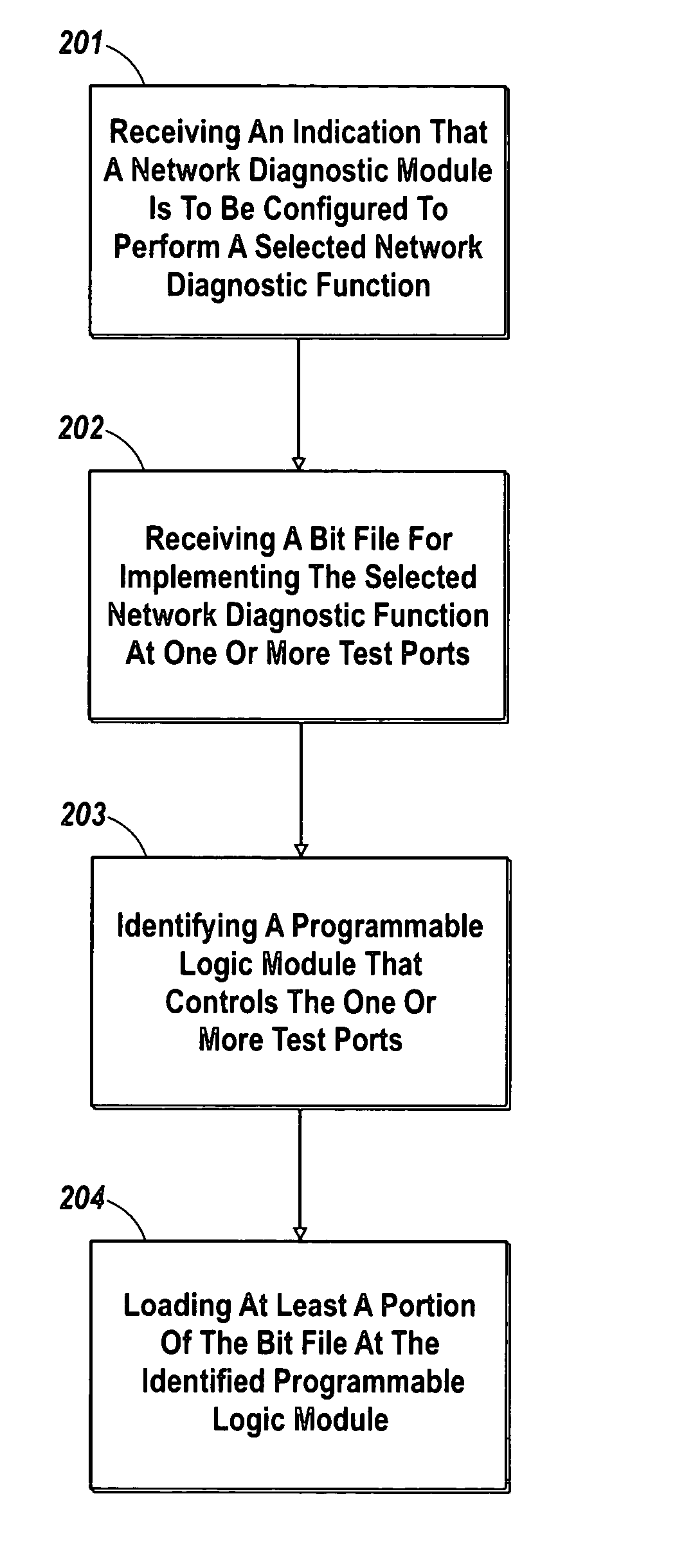
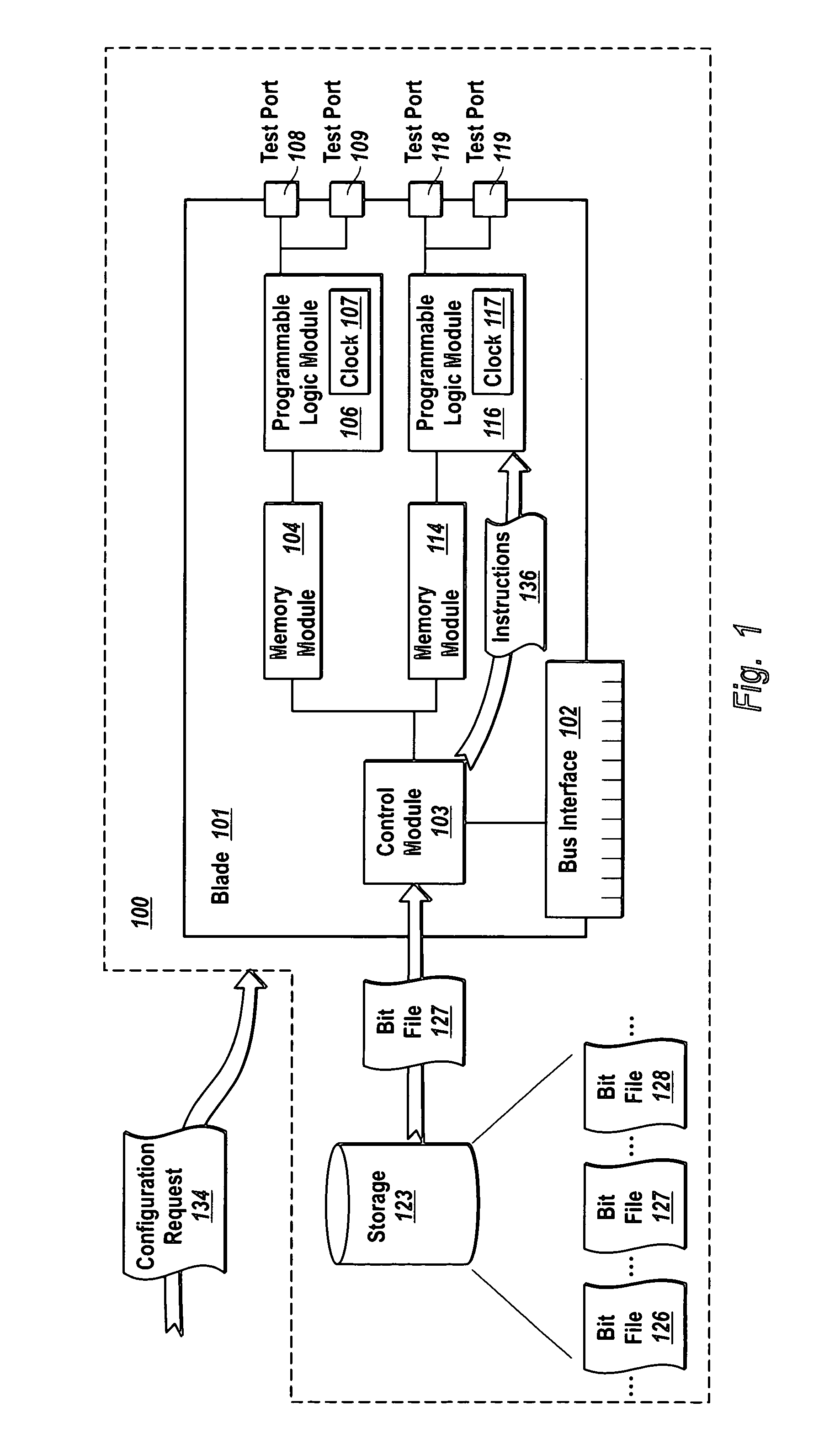
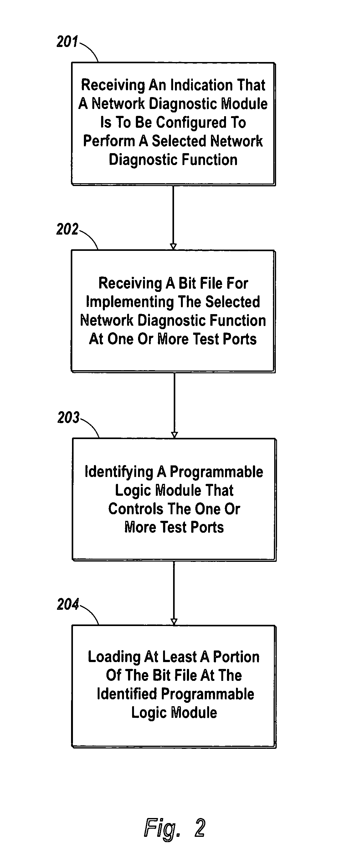
[0030] The principles of the present invention provide for network diagnostic modules that can be flexibly configured to perform any of a plurality of different network diagnostic functions. A computer system includes a network diagnostic module (e.g., on printed circuit board inserted into a PCI slot of the computer system). The network diagnostic module includes one or more programmable logic modules (e.g., one or more Field Programmable Gate Arrays (“FPGAs”) that have circuitry for implementing any of a plurality of network diagnostic functions (e.g., network analyzer, jammer, generator, bit error rate tester, etc). The network diagnostic modules receives an indication that the network diagnostic module is to be configured to perform a selected network diagnostic function (e.g., a network analyzer, jammer, generator, bit error rate tester, etc.)

[0031] The network diagnostic module receives a bit file with instructions for implementing the selected diagnostic function at one or m...


PUM


Abstract

The present invention provides for flexibly configurable network diagnostic modules that can implement any of a plurality of network diagnostic functions. A network diagnostic module receives an indication that a selected network diagnostic function (e.g., network analyzer, jammer, generator, bit error rate tester, etc.) is to be implemented. The network diagnostic module receives a bit file with instructions or data for implementing the selected network diagnostic function at one or more ports. The network diagnostic module identifies a programmable logic module (e.g., a Field-Programmable Gate Array (“FPGA”)) that controls the one or ports. The network diagnostic module loads a portion of the bit file at the identified programmable logic module to cause the programmable logic module and the one or more ports to interoperate to implement the selected network diagnostic function. A plurality of network diagnostic modules can be included in a common computer system chassis.

Description

1. CROSS REFERENCE TO RELATED APPLICATIONS [0001] The present application claims priority to U.S. Provisional Patent Application Ser. No. 60 / 498,070 entitled “Multi-Purpose Network Diagnostic Modules” filed Aug. 26, 2003, which is hereby incorporated by reference.BACKGROUND OF THE INVENTION [0002] 1. The Field of the Invention [0003] The present invention relates generally to identifying the cause of performance deviations and other problems in high speed data transmission systems and components. More particularly, embodiments of the present invention relate to configurable diagnostic modules that can perform a variety of different diagnostic tests suitable for use with various different network protocols and configurations. [0004] 2. Background and Relevant Art [0005] Computer and data communications networks continue to proliferate due to declining costs, increasing performance of computer and networking equipment, and increasing demand for communication bandwidth. Communications ...

Claims


Application Information

Patent Timeline
Patent Type & Authority Applications(United States)
IPC IPC(8): G06F15/173H04JH04L12/24
CPCH04L12/2697H04L41/0846H04L43/50H04L43/10H04L43/18H04L43/0823G06F15/16G06F15/173
Inventor DUBE, JEAN-FRANCOIS
Owner VIAVI SOLUTIONS INC
Why Eureka
Try Eureka