Method and equipment for simulation

a technology of simulation and equipment, applied in the field of simulation methods and equipment, can solve the problems of inability to obtain high accuracy, unexpected deformation, and large amount of local flare, and achieve the effects of high accuracy, high reliability, and easy and precise correction

Inactive Publication Date: 2005-03-03
FUJITSU SEMICON LTD
View PDF2 Cites 41 Cited by
  • Summary
  • Abstract
  • Description
  • Claims
  • Application Information

AI Technical Summary

Benefits of technology

[0013] According to the method and equipment for simulation of the present invention, even if traces equal to or smaller than an exposure wavelength are mixed in a pattern, it is possible to estimate the amount of local flare with extremely high accuracy, and precisely predict the occurrence of the local flare. The dimensions of traces are easily and precisely corrected based on simulation results, so that it is possible to actualize a highly reliable semiconductor device.

Problems solved by technology

The unevenness in the material of a lens of the exposure device and the specific characteristics thereof, however, cause scattering in the lens, so that the effect of scattering also has to be considered in the simulation.
The effect of scattering becomes a main cause of unexpected deformation in the shape of a transferred pattern and in the width of traces.
When there are traces the dimensions of which are equal to or smaller than the exposure wavelength, however, there is a problem that the amount of local flare cannot be obtained with high accuracy.

Method used


Image

  • Method and equipment for simulation
  • Method and equipment for simulation
  • Method and equipment for simulation

Examples


first embodiment

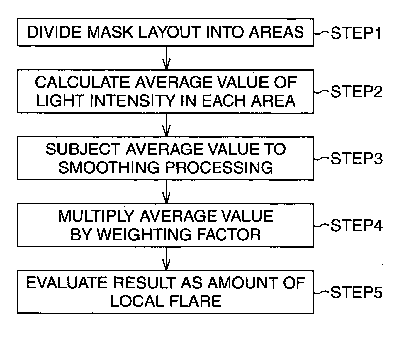
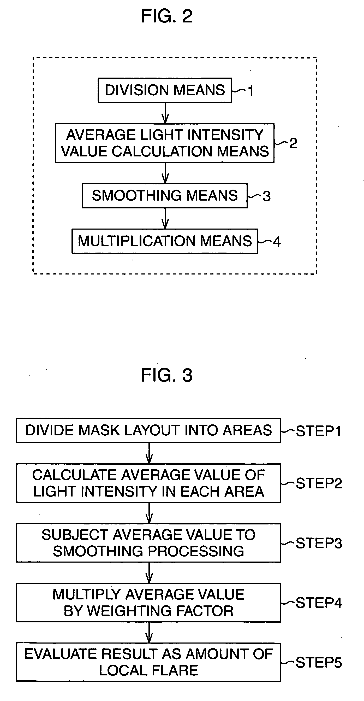
[0051] (First Embodiment)

[0052] In the first embodiment, the average value (relative value) of light intensity of a photo mask having a layout shown in FIG. 8 is obtained with the use of the method according to the present invention. The photo mask has a line-and-space pattern in which the width of an opening 11 is equal to that of a light shielding portion 12. It is assumed that the length “L” of the opening 11 is much longer than the width “W” thereof.

[0053]FIG. 9 is a graph of characteristics showing the relation between a line pitch in the photo mask and the value of light intensity.

[0054]FIG. 9 shows the average values of light intensity calculated by a method of the present invention, in relation to line pitches “P”. The average values of intensity transmittance according to a conventional method are also put therein for comparison purpose. In this embodiment, the average value is calculated on the condition that “NA” is 0.7, an exposure wavelength is 193 nm, and an interfer...

second embodiment

[0056] (Second Embodiment)

[0057] In the second embodiment, the amount of local flare calculated by the method of the present invention is added to an optical image by optical simulation, to obtain an optical image in consideration of local flare. In this embodiment, it is assumed that the ratio of the amount of local flare to the intensity of the optical image is 5%.

[0058]FIG. 10 shows the shape of a photo mask used in the calculation of this method. The photo mask identical to that of FIG. 7 has a line-and-space pattern in which the width of an opening 11 is equal to that of a light shielding portion 12 and has a line pitch of 0.5 μm. It is assumed that the length “L” of the opening 11 is much longer than the width “W” thereof.

[0059]FIG. 11 is a graph of characteristics showing the relation between the position in the photo mask and the value of light intensity. The position in FIG. 11 corresponds to the position in the photo mask along the broken line I-I of FIG. 10.

[0060]FIG. ...


PUM

PropertyMeasurementUnit
wavelengthaaaaaaaaaa
exposure wavelengthaaaaaaaaaa
widthaaaaaaaaaa

Abstract

The simulation equipment has division unit for dividing a layout of a photo mask (mask layout) into a plurality of areas, average light intensity value calculation unit for calculating an average value of light intensity in each of the areas, smoothing unit for subjecting the calculated average value to smoothing processing, and multiplication unit for multiplying the smoothed average value by a predetermined multiplier.

Description

CROSS-REFERENCE TO RELATED APPLICATIONS [0001] This application is based upon and claims the benefit of priority from the prior Japanese Patent Application No. 2003-308919, filed on Sep. 1, 2003, the entire contents of which are incorporated herein by reference. BACKGROUND OF THE INVENTION [0002] 1. Field of the Invention [0003] The present invention relates to a method and equipment for simulation which correct flare (local flare) locally occurring in the photo process of semiconductor manufacturing. [0004] 2. Description of the Related Art [0005] Pattern formation technology in manufacturing a semiconductor device adopts optical lithography. The optical lithography refers to a method in which a desired pattern formed in a reticle as a photo mask is transferred to a sample substrate through a reduction optical system. Photosensitive resin called a resist is formed on the sample substrate. With the use of difference in the melting speed between exposed areas and unexposed areas by d...

Claims


Application Information

Patent Timeline
Patent Type & Authority Applications(United States)
IPC IPC(8): G03F1/36G03F1/68G06F17/50G06G7/62G06K9/00H01L21/027
CPCG03F1/144G03F1/70
Inventor FUTATSUYA, HIROKIASAI, SATORU
Owner FUJITSU SEMICON LTD
Why Eureka
Try Eureka