Low-vibration shedding system

a shedding system and low vibration technology, applied in the field of systems, can solve the problems of shedding system and associated mechanism vibration, load on all elements, and inability to fully exploit the potential, and achieve the effects of good oscillation absorption, high axial rigidity, and good oscillation absorption properties

Inactive Publication Date: 2005-03-10
GROZ BECKERT KG
View PDF18 Cites 16 Cited by
  • Summary
  • Abstract
  • Description
  • Claims
  • Application Information

AI Technical Summary

Benefits of technology

[0013] With this as the point of departure, the object of the present invention is to create a mechanism in whose force transmission path at least one strap assembly is disposed, with a longitudinally oriented sandwich structure comprising different materials. At least one of the materials used has oscillation-absorbing properties. As a consequence of the longitudinal orientation, on the one hand a lightweight, low-mass construction and on the other good oscillatio

Problems solved by technology

As a rule, however, this potential cannot be fully exploited, because the existing shedding systems cannot withstand the loads that result from an overly high operating speed.
Although the most harmonic possible motions are sought here and achieved, nevertheless vibration occurs in the shedding system and the associated mechanism that connects the heddle shafts with the eccentric machines.
This vibration puts a load on all the elements of the shedding system and leads to premature wear or breakage of components

Method used


Image

  • Low-vibration shedding system
  • Low-vibration shedding system
  • Low-vibration shedding system

Examples


Embodiment Construction

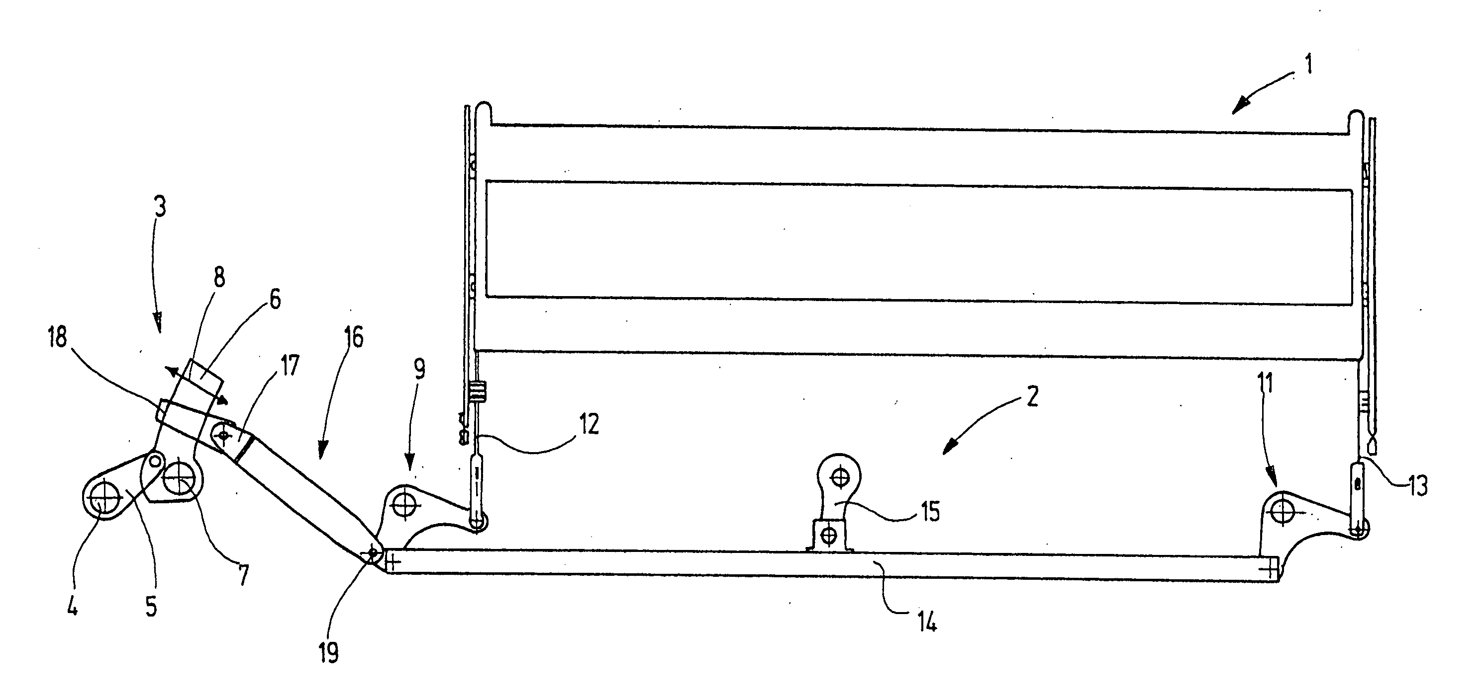
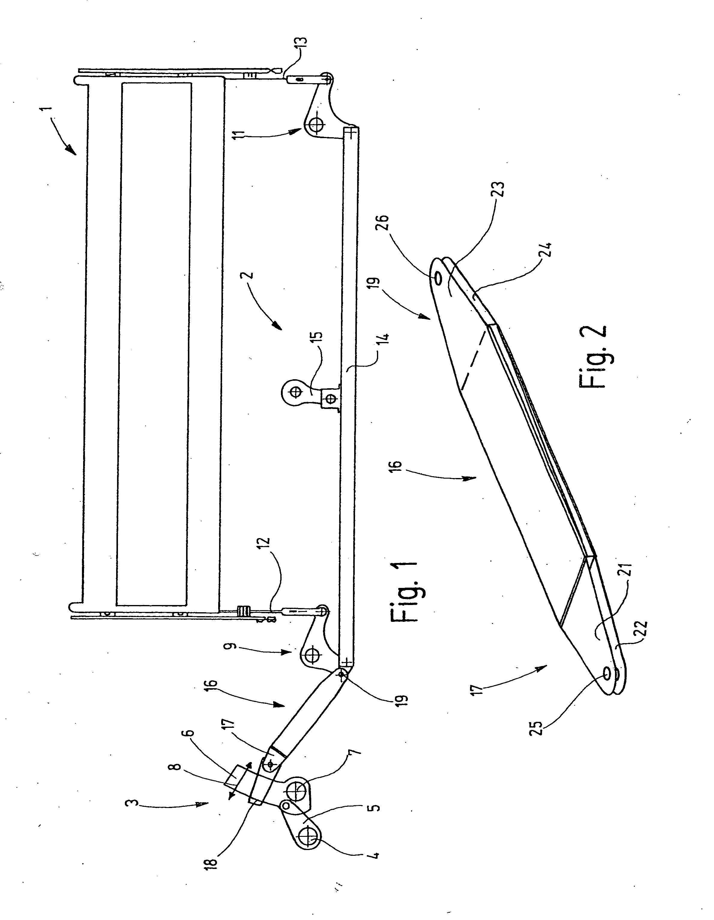
[0030] In FIG. 1, a heddle shaft 1 is shown, which for shedding purposes is disposed on a power loom, not otherwise shown, and is driven via a rod linkage 2 by a shaft machine 3. The shaft machine 3 is for instance an eccentric machine having an eccentric 4, which via a connecting rod 5 drives a sword 6, serving as a power takeoff mechanism, back and forth. The sword 6 is pivotably supported about a center of pivoting 7. Its pivoting motion is represented in FIG. 1 by an arrow 8.

[0031] The rod linkage 2 serving to transmit the reciprocating pivoting motion of the sword 6 to the heddle shaft 1 includes, in the present exemplary embodiment, at least two pivotably supported bell crank levers 9, 11, which are joined to the heddle shaft 1 via tension and pressure rods 12, 13 in order to move the heddle shaft up and down. The lower arms of the bell crank levers 9, 11 are joined to one another by a connecting bar 14, which is pivotably connected to the respective arms of the bell crank le...


PUM

PropertyMeasurementUnit
Thicknessaaaaaaaaaa

Abstract

A novel rod linkage for driving a heddle shaft includes at least one strap (16), which for damping oscillation has a sandwich structure (37) oriented in the longitudinal direction (L) of the strap assembly (16). The sandwich structure includes at least one rigid element (27), extending in the longitudinal direction, which is joined to one end (17) of the strap assembly (16); a second rigid element (31), likewise extending essentially in the longitudinal direction, which is joined to the other end (19); and a two-dimensional damping element (34), again extending in the longitudinal direction, disposed between the first two. The element (34) exclusively effects the mechanical connection of the two parts (16a, 16b) of the strap assembly (16). Preferably, no additional connecting elements, such as rivets, screws, or other rigid connections, between the rigid elements (27, 31) are provided. Preferably, the rigid elements (27, 31) are embodied as wedges pointing in opposite directions, which thus define a wave resistance that varies in opposite directions in the longitudinal direction. This wave resistance brings about an intentional coupling misadaptation with respect to the oscillation transmission. The element (34) disposed between them damps the oscillations additionally, so that the strap assembly (16) transmits driving motions like a filter and destroys or absorbs interfering oscillations.

Description

CROSS REFERENCE TO RELATED APPLICATION [0001] This application claims the priority of German Patent Application No. 103 41 629.3, filed on Sep. 10, 2003, the subject matter of which, in its entirety, is incorporated herein by reference. FIELD OF THE INVENTION [0002] The invention relates to a system for driving a heddle shaft of a power loom. BACKGROUND OF THE INVENTION [0003] Power looms have so-called shedding systems, which serve to move warp yarns upward or downward out of the warp yarn plane in order to form a so-called shed so that a weft yarn can be inserted. The weft yarn insertion systems, which employ water or air, for instance, have a power potential for maximum weaving speeds. As a rule, however, this potential cannot be fully exploited, because the existing shedding systems cannot withstand the loads that result from an overly high operating speed. The loads result from the accelerations in the up-and-down motion of the shafts with which the heddles are retained. The mo...

Claims


Application Information

Patent Timeline
IPC IPC(8): F16H21/10D03C1/14D03C1/16D03C5/00D03C9/06D03C13/00D04B1/14
CPCD03C1/16D03C9/0691D03C9/0683
Inventor BRUSKE, JOHANNESBUCHLE, GUNTHER
Owner GROZ BECKERT KG
Why Eureka
Try Eureka