Inkjet recording head assembly and inkjet recording apparatus

a technology of inkjet recording and recording head, which is applied in the direction of printing, etc., can solve the problems of reducing the quality of the recorded image, limiting the design of the device, and allowing no design freedom, so as to reduce the size of the apparatus, simplify the movement mechanism of the cap, and achieve more freedom

Inactive Publication Date: 2005-03-10
FUJIFILM HLDG CORP
View PDF8 Cites 56 Cited by
  • Summary
  • Abstract
  • Description
  • Claims
  • Application Information

AI Technical Summary

Benefits of technology

[0035] Also, the inkjet recording apparatus relating to another aspect of the present invention further comprises a suction cap adapted to closely fit a nozzle surface of the recording head, the suction cap having a segmented structure divided into an exhaust side support and a nozzle side support by an inner partitioning wall, the suction cap having a configuration in which one of the exhaust side support and the nozzle side support is selectively connected to the pressure reduction device through the connection-switching device. Making the cap to perform a dual role allows the cap structure with a cap movement mechanism to be simplified.
[0036] According to the present invention, more freedom is allowed with design, and the size of the apparatus can be reduced because of a configuration in which the auxiliary tank and the recording head are integrated without tubes, a circulation channel is formed between the auxiliary tank and the head, and the pressure reduction device can be connected to the auxiliary tank. Also, the infusion of air bubbles from the liquid feed tube can be prevented, and air bubbles mixed in the head can be efficiently removed by circulating the ink and reducing the pressure in the auxiliary tank.
[0037] According to the present invention, the efficiency of circulating ink in a full-line head or other such long-length head can be improved, and it is possible to achieve objects such as shortening the time to remove air bubbles, reducing the amount of ink consumed, and improving the ink supply (refill) properties to the nozzles. Thus, it is possible to quickly improve productivity in printing.
[0038] Furthermore, according to another aspect of the present invention, the structure of the apparatus can be simplified by making the nozzle-suctioning pump or the cap to perform a dual role.

Problems solved by technology

In such an inkjet recording apparatus, the ink discharge from the nozzles becomes unstable when air bubbles or the like are mixed in the recording head, the amount of ink discharged (the dot size resulting from the deposited droplet on the recording paper) and the droplet deposition position (flight direction of the ink) vary, and the quality of the recorded image is reduced.
However, in the structure proposed in conventional practice, the sub-tank must be installed on the lower side of the head because negative pressure corresponding to the amount of liquid pumped by the sub-tank and nozzles is applied inside the head.
This is a restriction on the design of the device and allows no freedom in design.
However, the tube connecting the sub-tank and the recording head is susceptible to taking in air bubbles from the outside air, so the diameter of the tube cannot be too large and is limited to a specific value or less.
However, handling becomes complex and the device increases in size when the number of tubes is increased.
Furthermore, the overall extension of the ink flow channel is lengthened, which makes it more difficult for the ink solution to circulate.
Particularly, when using a large head such as a line head (a so-called full-line recording head) having a row of nozzles extending over the entire width of the printing medium in a direction substantially orthogonal to the conveyance direction of the medium, it becomes extremely difficult to circulate the ink, and air bubbles and the like in the head cannot be efficiently discharged.

Method used


Image

  • Inkjet recording head assembly and inkjet recording apparatus
  • Inkjet recording head assembly and inkjet recording apparatus
  • Inkjet recording head assembly and inkjet recording apparatus

Examples


Embodiment Construction

[0055] General Configuration of an Inkjet Recording Apparatus

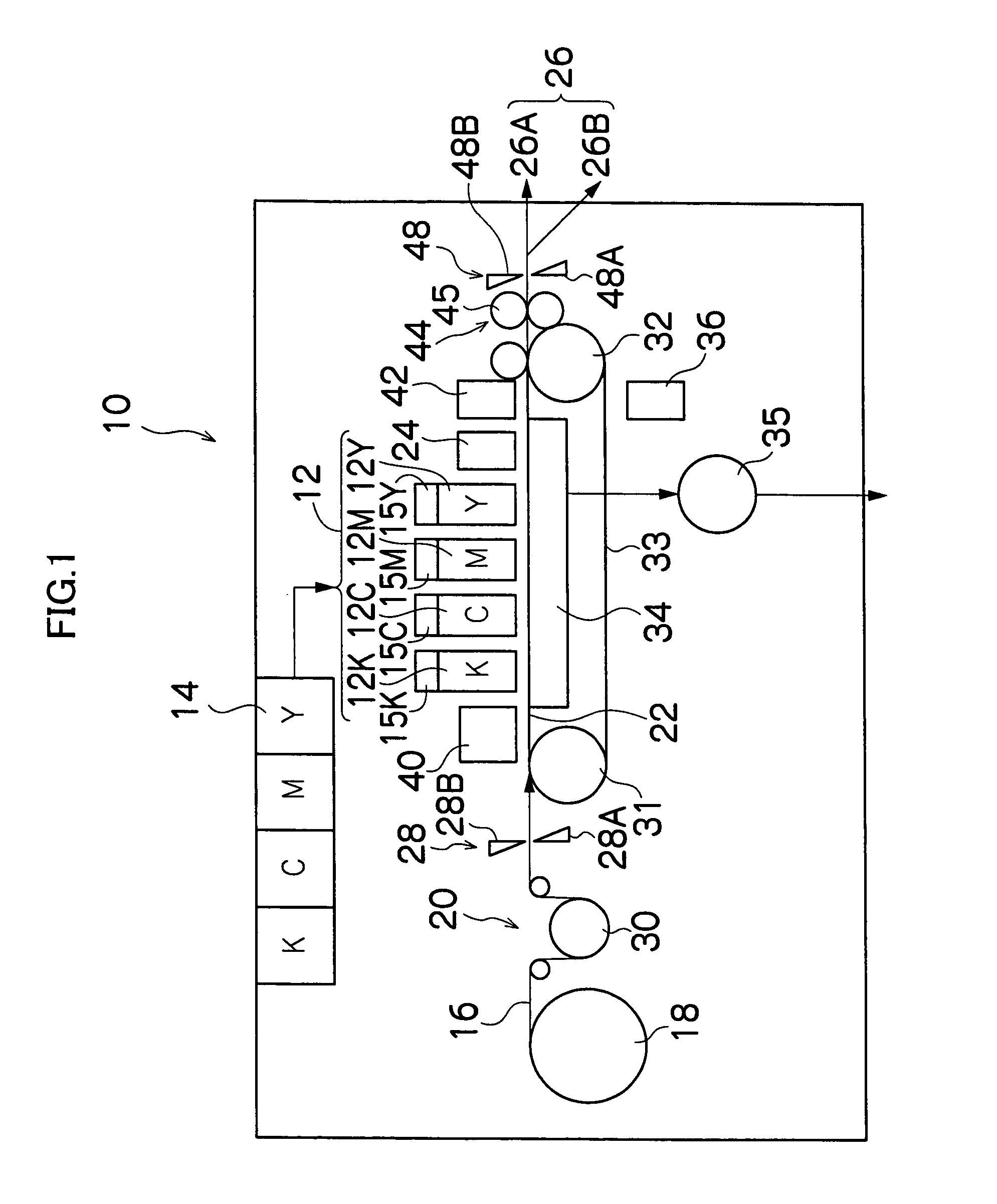
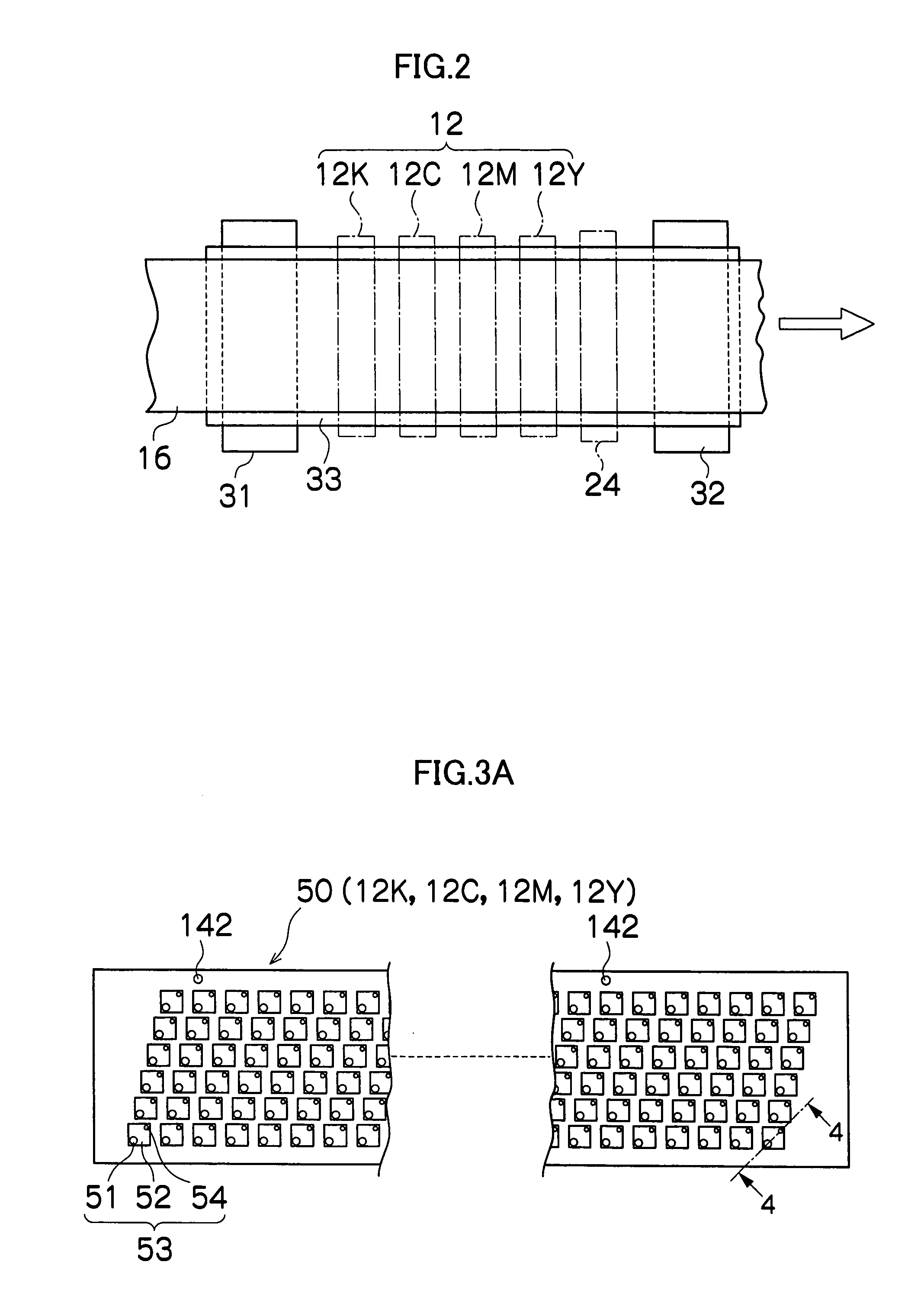
[0056]FIG. 1 is a general schematic drawing of an inkjet recording apparatus according to an embodiment of the present invention. As shown in FIG. 1, the inkjet recording apparatus 10 comprises: a printing unit 12 having a plurality of print heads 12K, 12C, 12M, and 12Y for ink colors of black (K), cyan (C), magenta (M), and yellow (Y), respectively; an ink storing / loading unit 14 for storing inks to be supplied to the print heads 12K, 12C, 12M, and 12Y; sub-tanks 15K, 15C, 15M, and 15Y integrally mounted on top of the print heads 12K, 12C, 12M, and 12Y; a paper supply unit 18 for supplying recording paper 16; a decurling unit 20 for removing curl in the recording paper 16; a line CCD sensor 21 for determining the shape, orientation, and position of the recording paper 16; a suction belt conveyance unit 22 disposed facing the nozzle face (ink-droplet ejection face) of the print unit 12, for conveying the recording paper 1...


PUM


Abstract

The inkjet recording head assembly comprises: a recording head which has nozzles discharging ink; a main tank which is a supply source of the ink; and an auxiliary tank which communicates with the main tank, the auxiliary tank being in direct connection to the recording head without interposing tubes, a circulation channel being formed by the auxiliary tank and an ink flow channel in the recording head, the auxiliary tank having an exhaust channel connected to a pressure reduction device which reduces inner pressure of the auxiliary tank.

Description

BACKGROUND OF THE INVENTION [0001] 1. Field of the Invention [0002] The present invention relates to an inkjet recording apparatus, and particularly relates to a structure of an ink supply system suitable for a full-line recording head having a nozzle row wherein a plurality of ink discharging nozzles are arrayed over a length corresponding to the entire width of a printing medium in the direction substantially orthogonal to the feed direction of the printing medium. [0003] 2. Description of the Related Art [0004] An inkjet-type recording apparatus deposits ink droplets on a printing medium by moving recording paper or another such printing medium relative to a recording head with nozzles and discharging ink from the nozzles according to a print signal, and forms an image on the printing medium by means of the inkjet. In such an inkjet recording apparatus, the ink discharge from the nozzles becomes unstable when air bubbles or the like are mixed in the recording head, the amount of ...

Claims


Application Information

Patent Timeline
Patent Type & Authority Applications(United States)
IPC IPC(8): B41J2/175
CPCB41J2002/14459B41J2/175
Inventor INOUE, HIROSHI
Owner FUJIFILM HLDG CORP
Why Eureka
Try Eureka