Magnetoresistive spin-valve sensor and magnetic storage apparatus

a technology which is applied in the field magnetic storage apparatus, can solve the problems of generating noise, deteriorating thermal stability of magneto-resistive spin-valve sensor, and difficulty in maintaining a small coercive field and a small interlayer coupling field between the pinned layer and the free layer

Inactive Publication Date: 2005-03-10
FUJITSU LTD
View PDF13 Cites 28 Cited by
  • Summary
  • Abstract
  • Description
  • Claims
  • Application Information

AI Technical Summary

Benefits of technology

[0010] Accordingly, it is a general object of the present invention to provide a novel and useful magnetores

Problems solved by technology

However, when the thickness of the free layer decreases, it is difficult to maintain a small coercive field and a small interlayer coupling field between the pinned layer and the free layer.
As a result, the thermal stabili

Method used


Image

  • Magnetoresistive spin-valve sensor and magnetic storage apparatus
  • Magnetoresistive spin-valve sensor and magnetic storage apparatus
  • Magnetoresistive spin-valve sensor and magnetic storage apparatus

Examples


Embodiment Construction

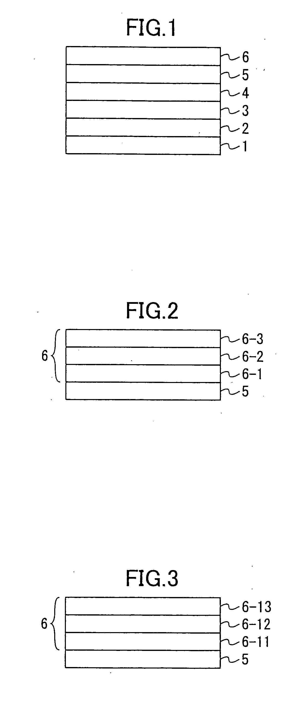
[0039] A description will be given of a first embodiment of a magnetoresistive spin-valve sensor according to the present invention, by referring to FIG. 1. FIG. 1 is a cross sectional view showing an important part of this first embodiment of the magnetoresistive spin-valve sensor according to the present invention. The magnetoresistive spin-valve sensor shown in FIG. 1 includes a substrate 1, an underlayer 2, an antiferromagnetic layer 3, a first magnetic layer 4, a spacer layer 5, and a second magnetic layer 6.

[0040] For example, the underlayer 2 has a multi-layer structure including a Ta layer and a NiFe layer formed on the Ta layer. Further, the antiferromagnetic layer 3 is made of PdPtMn, for example, and forms a pinning layer.

[0041] The first magnetic layer 4 is made of a magnetic material such as a Co alloy, and may have a single-layer structure or, a multi-layer structure as in the case of the second magnetic layer 6 which will be described later. The first magnetic layer...


PUM


Abstract

A magnetoresistive spin-valve sensor includes a first layer made of a magnetic material, a second layer made of a magnetic or nonmagnetic material and disposed on the first layer, and a third layer made of a magnetic material and disposed on the second layer, where the first, second and third layers form a free layer having a multi-layer structure.

Description

[0001] This application is a continuation application filed under 35 U.S.C. 111(a) claiming the benefit under 35 U.S.C. 120 and 365(c) of a PCT International Application No. PCT / JP02 / 01669 filed Feb. 25, 2002, in the Japanese Patent Office, the disclosure of which is hereby incorporated by reference. [0002] The PCT International Application No. PCT / JP02 / 01669 was published in the English language on Aug. 28, 2003 under International Publication Number WO 03 / 071300 A1.BACKGROUND OF THE INVENTION [0003] 1. Field of the Invention [0004] The present invention generally relates to magnetoresistive spin-valve sensors and magnetic storage apparatuses, and more particularly to a magnetoresistive spin-valve sensor having a structure for improving an output thereof, and to a magnetic storage apparatus which uses such a magnetoresistive spin-valve sensor. [0005] 2. Description of the Related Art [0006] A typical magnetoresistive spin-valve sensor includes a base layer, a first magnetic (pinned...

Claims


Application Information

Patent Timeline
IPC IPC(8): G01R33/09G11B5/00G11B5/39H01F10/13H01F10/32H01L43/08H01L43/10
CPCB82Y10/00B82Y25/00G01R33/093G11B2005/3996G11B5/3903G11B5/3906G11B5/00
Inventor HONG, JONGILLKANAI, HITOSHI
Owner FUJITSU LTD
Why Eureka
Try Eureka