Lighting device and lighting fixture for a vehicle

a technology for lighting devices and vehicles, which is applied in the direction of lighting support devices, discharge tubes luminescnet screens, instruments, etc., can solve the problems that the lighting device using a light emitting device has not yet fulfilled the requirements as a lighting fixture, and the conventional lighting device has not yet fulfilled the requirements. , to achieve the effect of excellent light distribution, long operating life and high luminan

Active Publication Date: 2005-03-10
NICHIA CORP
View PDF10 Cites 92 Cited by
  • Summary
  • Abstract
  • Description
  • Claims
  • Application Information

AI Technical Summary

Benefits of technology

[0008] The objects of the present invention include using a light emitting device as a lighting device in order to illuminate a specific area, and t...

Problems solved by technology

However, conventional lighting devices have yet to fulfill these requirements.
However, a lighting device using a light emitting device has not yet fulfilled the requirements as a li...

Method used


Image

  • Lighting device and lighting fixture for a vehicle
  • Lighting device and lighting fixture for a vehicle
  • Lighting device and lighting fixture for a vehicle

Examples


embodiment 1

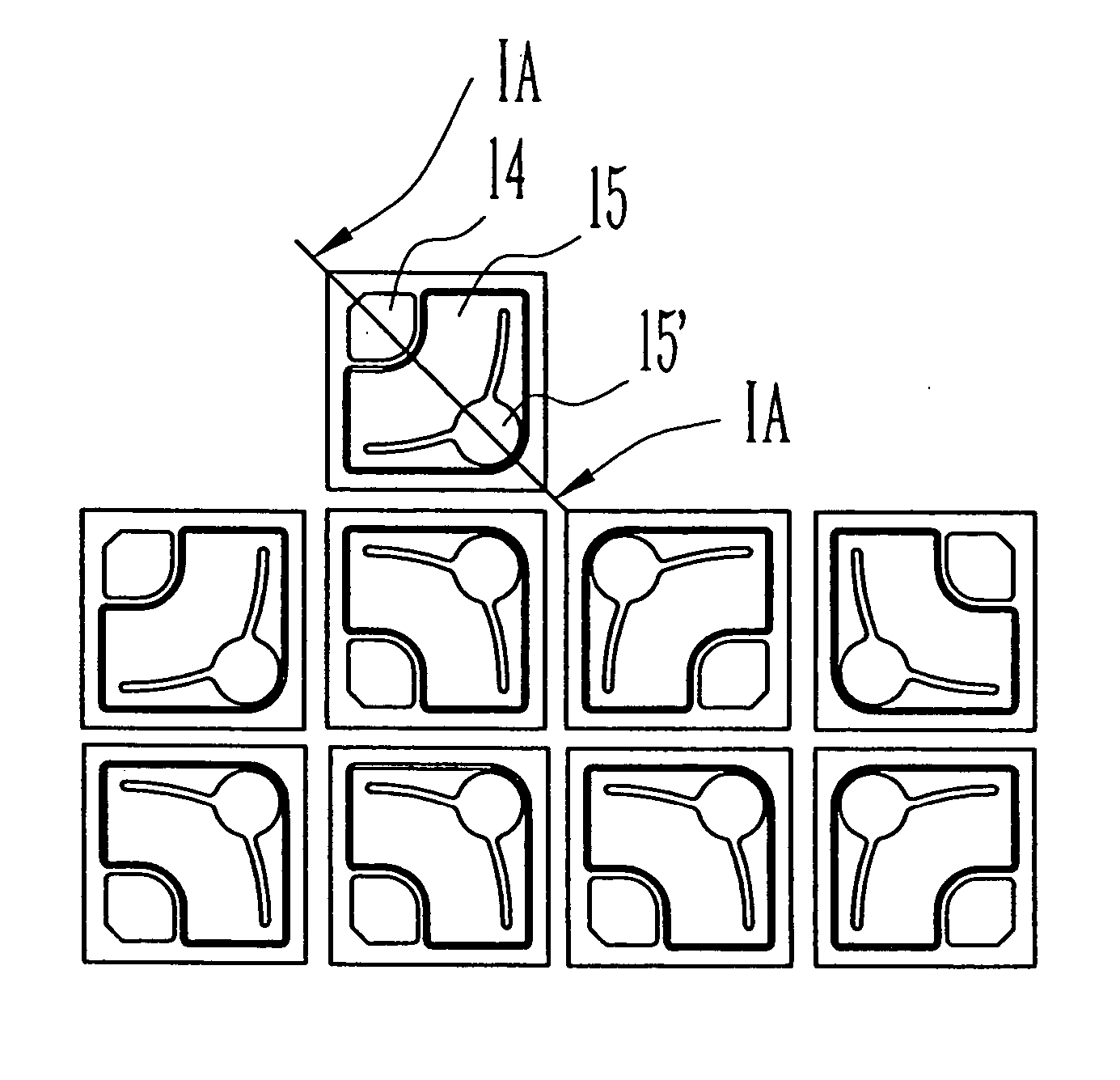
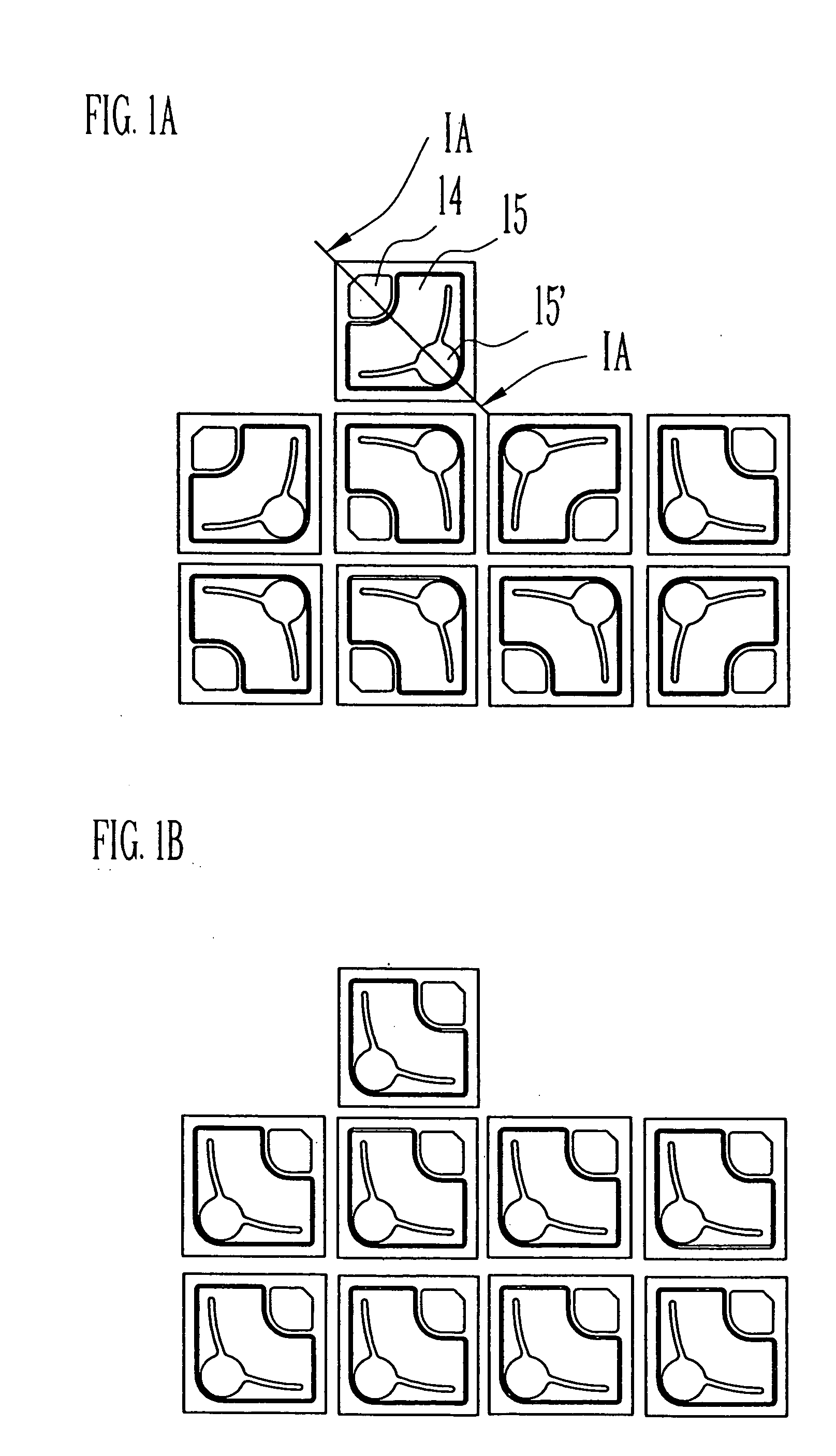
[0066] In the lighting device of the present invention, a plurality of the light emitting devices are arranged so as to form almost the same light distribution pattern as the light distribution pattern for a vehicle. The light distribution pattern for a vehicle has a predetermined horizontal cut-off line section on the top of one side of a central vertical line and an oblique cut-off line section whose central line end being lowered in another end. Also, the light emitting diode is preferably comprised of a nitride semiconductor layer and a pair of electrode layers. Moreover, a fluorescent material layer, to be excited by the emission from the light emitting device, can be provided on the surface of the light emitting device.

[0067] Moreover, in the light fixture for a vehicle of the present invention, the luminescent surface of the light emitting device in the above-described lighting device is arranged in a perpendicular direction, and a reflective member having a parabolic surfac...

embodiment 2

[0072] The light emitting device used in the lighting device in the present embodiment mainly comprises a nitride semiconductor layer and a pair of the electrode layers. The luminescent surface of the light emitting device is configured so as to form a light distribution pattern almost the same as the light distribution pattern for a vehicle. Further, a fluorescent material layer excited by the light emitted from the nitride semiconductor layer can also be disposed on the surface of the light emitting device. In this lighting device, a single light emitting device can compose a lighting device, or a plurality of light emitting devices can compose a lighting device.

[0073] In the lighting device of the present embodiment, the luminescent surface of the light emitting device is formed so as to form a light distribution pattern almost the same as the light distribution pattern for a vehicle, in other words, formed into the shape capable of composing the light distribution pattern.

[007...

embodiment 3

[0080] The light emitting device of the present invention is provided with a fluorescent material layer whose excitation source is the irradiation on the surface thereof. Moreover, the light emitting device is preferably comprised of the nitride semiconductor layer and a pair of electrode layers. The fluorescent material layer may also be formed so as to show a high luminance, high color rendering properties, or both thereof, by a portion of irradiation from the light emitting device. In this lighting device, either a single light emitting device or a plurality of light emitting devices can be used.

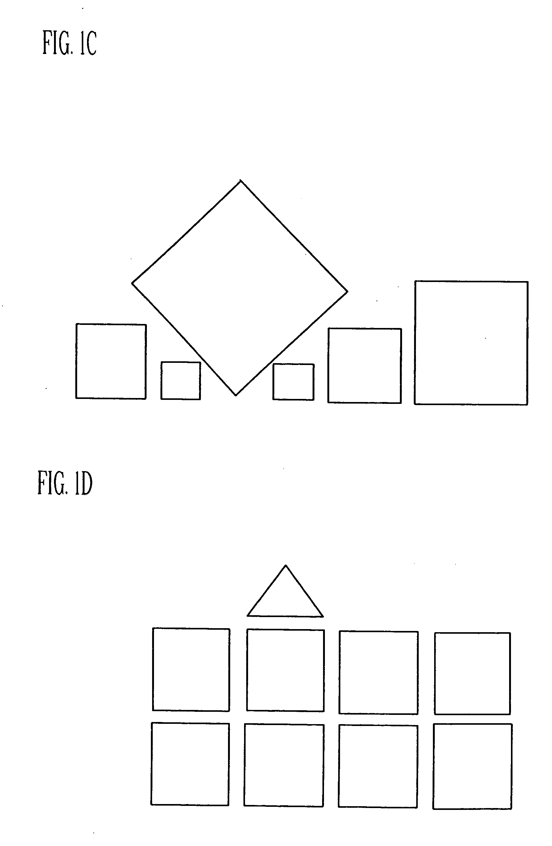
[0081] Also, it is preferable that the light emitting device of the present invention be constructed so as to form a light distribution pattern in accordance with the size and shape of the object to be illuminated. For this, it is suitable to form the shape of the luminescent surface of the light emitting device so as to correspond to a desired light distribution pattern. That is, it is ...


PUM


Abstract

The light distribution pattern for a vehicle having a predetermined horizontal cut-off line section at the top portion on one side of the vertical central line and an oblique cut-off line section whose central line side is lowered in another side, and the light distribution pattern of the light source comprising a plurality of semiconductor light emitting devices are almost the same shape. Moreover, the light distribution pattern of the light source is formed by arranging a plurality of semiconductor light emitting devices with a configuration almost the same shape as the light distribution pattern for a vehicle. The semiconductor light emitting device has a luminance surface whose configuration is almost the same shape as the light distribution pattern for a vehicle. Further, the light source comprising the semiconductor light emitting device includes a fluorescent material whose excitation source is the emission from the nitride semiconductor device and a part of region of the fluorescent material emits light with higher luminance or higher color rendering properties compared with the other regions.

Description

BACKGROUND OF THE INVENTION [0001] 1. Field of the Invention [0002] The present invention relates to a lighting device and a lighting fixture for a vehicle and more particularly to a lighting device and a lighting fixture for a vehicle comprising a light emitting device including a nitride semiconductor layer. [0003] 2. Discussion of the Related Art [0004] Recently development of light emitting devices with high luminance has advanced and light emitting devices have become available for various sources of light in our life. For example, Japanese Patent Application Publication No. 2001-155510 (pages 2 to 3, FIG. 1 and FIG. 5) discloses a lighting device using the combination of a light emitting device and a reflector in order to distribute light from the light emitting device in a narrow angle for a pavement marker with automatic luminescence trigger which is installed in a roadway surface or a wall surface. [0005] Such lighting devices are required to have characteristics capable of...

Claims


Application Information

Patent Timeline
IPC IPC(8): C09K11/08F21S8/10H01L25/075H01L33/20H01L33/38
CPCC09K11/08F21S48/1159F21S48/1163F21S48/1747F21Y2101/02H01L25/0753H01L2924/0002H01L33/20H01L33/38H01L2924/00F21Y2115/10F21S41/143F21S41/155F21S41/18F21S41/663F21S41/148F21S41/153
Inventor YAMADA, MOTOKAZUNAITOU, TAKAHIRO
Owner NICHIA CORP
Why Eureka
Try Eureka